

Electricity use is expected to grow for water and wastewater treatment (WWT) due to the increasing population and new regulations. Pumping of all sorts is the largest consumer of electricity in water supply systems and, to a small extent, in treatment systems. Electricity consumption is a large percentage of the variable cost makeup of a water facility. A 2013 Electric Power Research Institute (EPRI) report1 showed that applying variable frequency drives (VFDs) to motor-driven pumps is a critical enabler for lowering energy consumption. However, in any industrial facility, a large part of the electric consumption is from fixed-speed induction motors spread across various processes. Induction motors being a lagging load drag down the overall plant power factor.

Electric power quality is one of the key concerns in any facility’s power delivery apparatus design. Power factor is a measure of overall power quality. Poor power factor leads to excessive current requirements and inefficient usage of upstream equipment such as transformers, generators and the distribution system. Large users of electricity, such as industrial plants, exacerbate these inefficiencies. Electric utilities penalize the consumer (plant) through additional charges as a part of their electric bill. Electric utilities typically charge based on the energy consumed per kilowatt-hour ($/kWhr). However, depending on the utility provider, large electricity users are also billed for poor power factor. At first, these charges might not be easily recognizable in an electric bill. However, a closer look at the contracted electric tariff structure and the corresponding monthly statement will show how and to what extent the consumer is subject to power factor penalties. The two most common ways of assessing a power factor penalty are:
- Adjusting the billed power demand (kW) by multiplying the actual power demand (kW) by 0.95 or 0.90 and dividing it by the plant’s unique power factor. In simple terms, the plant is subject to power factor penalties if it cannot maintain the threshold power factor of 0.95 or 0.90 lagging. Image 1 represents this tariff structure.
- Directly charge for the reactive power demand ($/kilo volt amps reactive [kVAr]) as metered by the utility provider. Image 2 represents this tariff structure.
Multiple solutions exist to reduce or eliminate power factor penalties. Fixed or switched capacitor banks are commonly applied to improve power factor. They are relatively low cost and easily applied. However, the proliferation of several nonlinear (harmonic generating) loads such as LED lights, low-voltage VFDs and others, when combined with shunt capacitor banks, can lead to electrical resonance damaging the capacitors themselves, over-exciting motors and other erratic behavior. While active/passive filters exist, they must be carefully applied in a system.
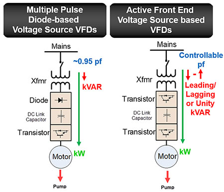
Voltage source inverter (VSI)-based active front end (AFE) VFDs provide a convenient solution. When applied correctly, they can provide energy savings through speed control while providing dynamic reactive power (kilovolt-ampere-reactive, or kVAR) to improve the power factor. This capability eliminates or reduces the need for power factor correction capacitors. Depending on the electricity tariff structure and the overall load profile, a facility could realize thousands of dollars of savings a year by reducing or eliminating power factor penalties and the ongoing maintenance costs of capacitors. Image 3 shows the major medium-voltage VFD topologies from a front-end converter and line-side power factor standpoint.
Multipulse diode-based converters common in the industry maintain a minimum of 0.95 lagging power factor across most of the operating envelope of the pump. However, power factor can drop below 0.95 at low loads and speeds. The VSI-based AFEs can regulate the power factor and operate in leading, lagging or unity power factor modes. This is because the rectifier section of the VFD is constructed using an active power semiconductor device such as a transistor (insulated-gate bipolar transistor is the most commonly used transistor) and the DC link is a capacitor. A detailed explanation of how this VFD can control power factor is explained in Reference 2. This article aims to show through a simple system the impact of each topology of the VFD and how the AFE-based VSI drive can help improve power factor.
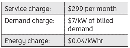
Consider a hypothetical facility with a single 1,800-horsepower (hp), 4,160-volt (V) VFD-driven pump along with a 2-megawatt (MW) load that might consist of other processes and fixed speed electric motors. Assume that the 2-MW load is at 0.8 power factor (lagging). The utility that services this load has the following tariff structure: The utility states that the billed demand is calculated by multiplying the actual power demand (kW) by 0.95 and dividing it by the plant’s unique power factor.
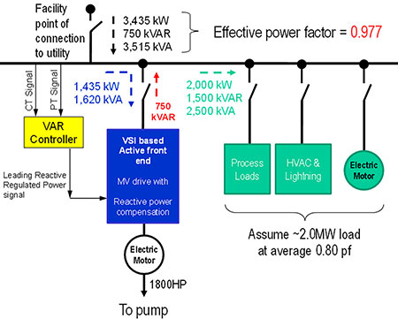
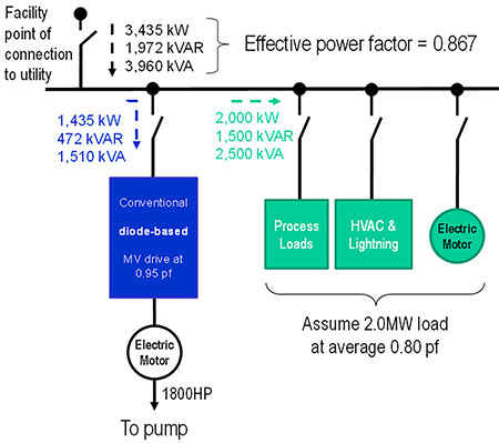
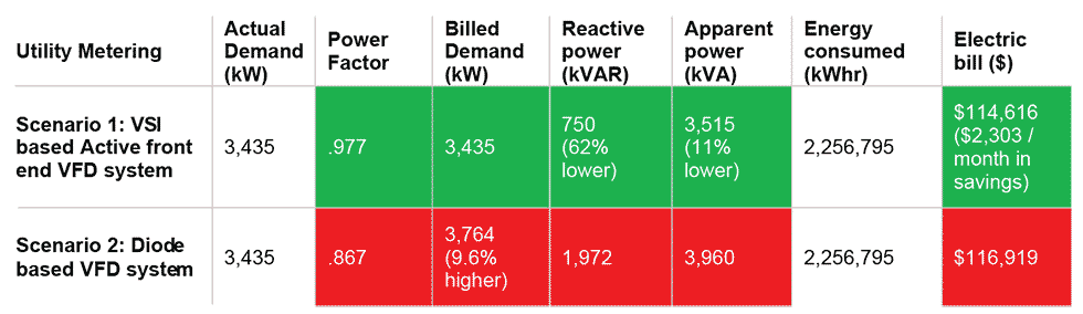
For simplicity’s sake, assume the entire facility runs at a steady load for 90% of the time (657 hours per month). Image 4a shows how the AFE-based VSI drive can improve the power factor without the need for capacitor banks and reduce electricity charges. This is because the VSI-based AFE drive can produce leading reactive power to compensate for the lagging reactive power demanded by the 2-MW load. Compare this to a conventional multipulse diode-based VFD (Image 4b) and one can see that the facility will be penalized for low power factor. The commercial impact of these two topologies of VFD is shown in Image 5.
What is shown above is only the savings that one can observe in the electric bill. If the facility decides to apply capacitor banks in case a diode front-end VFD topology is selected, one will need to add in the capital expenditure (capex) and operating expenditure (opex) costs of the capacitor bank. In this case, the facility would need an 841-kVAR capacitor bank to meet the 0.95 threshold power factor or a penalty could be paid in the form of higher electric bills. However, in the voltage source inverter (VSI)-based AFE drive, the user need not install any additional equipment. The VFD, by virtue of its topology, offers pump speed control and reactive power compensation.
VFD topology selection for pumps has a material impact on the overall capex and opex costs of a water or water treatment facility. With the pandemic bringing fresh challenges to city budgeting, every dollar saved in operations directly reduces deficits without corresponding tax increases. It is important to open new lines of engineering and economic thinking for selecting and applying large drives for pumping which, per Reference 1, are the most significant users of electricity. The value of the VSI-based AFE drive is monetizable only if the water facility is subject to an electricity tariff that has a power factor component in its billing. In a straight-up energy charge ($/kWhr) billing structure common among residential customers, this technology’s benefit is in terms of power capacity (kVA) freed up in distribution transformers, reduced line losses and more optimal sizing of electrical equipment. Further, some in the industry might be concerned about the bus voltage rise that might result due to the ASD running at the leading power factor. While this is possible in switched capacitor banks due to the discrete nature of how reactive power is compensated, this is not the case with VSI-based AFE drives since the leading kVARs generated are regulated. In fact, this technology can be used in concert with existing cap banks to provide the necessary reactive power “trim” control for the overall system. To see how VFDs can impact electricity charges, it is best for the facility personnel or the engineering consultant to engage with the VFD manufacturer to run a basic technical and economic analysis on this technology before designing a system or, at a minimum, before a request for quote (RFQ) specification is developed.
References
- S. Pabi, A. Amarnath, R. Goldstein, L. Reekie, “Electricity Use and Management in the municipal water supply and wastewater Industries,“ Joint EPRI & WRF report, November 2013, 3002001433, sciencetheearth.com/uploads/2/4/6/5/24658156/electricity_use_and_management_in_the_municipal_water_supply_and_wastewater_industries.pdf. Date accessed: Nov. 23, 2020.
- tmeic.com/sites/default/files/assets/files/library/Exceptional%20-%20MVe2ReactivePowerControl-D0007-103Feb2019-web.pdf.
