

In my last column (read it here), we reviewed the analysis process and discussed several ways to structure the cause and effect analysis phase. For example, one could use:
- an Excel spreadsheet
- a mind map
- a fishbone or Ishikawa diagram
As I mentioned in my June 2020 column, we will use the fishbone for the cause and effect process. In the previous column, we established the four major bones, which are now noted in Image 1.
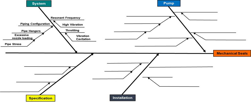 IMAGE 1: The fishbone diagram explores the cause and effect of the system (Image courtesy of the author)
The next step is to populate the sub-bones by identifying the potential causes and subsequent effects that are relative to the four categories.
Cause & Effect
Cause & Effect
Cause = The reason for something happeningEffect = What happened
Cause + Effect = Explains why things happen
As with all of the other steps in the root cause failure analysis, the cause and effect process is important. Failure to identify a potential cause may lead the analysis team down the wrong path. The same can be said for effect.
Cause and effect are defined as a relationship between events or things, where one is the result of the other or others. This is a combination of action and reaction.
Cause and effect links add an element of critical thinking to the process. A cause is an action or event that results in another action or event.
What does cause and effect look like when we apply it to a pumping system?
There are multiple failure modes that have been identified:
- mechanical seals
- bearings
- coupling shim packs
Therefore, it would be best to break down and analyze each failure independently. In other words, we will use a separate fishbone, or cause and effect diagram, for each failure mode.
As the cause and effect progresses to the bearing and shim pack, we may begin to see contributing factors. One or more of the failure modes may be a contributing factor to another.
Mechanical Seal Failures
Let us begin with the mechanical seal failure. According to plant personnel, the boiler feedwater system under examination was upgraded in 1988. Since then, startup and commissioning to mechanical seals have experienced frequent failures (replaced with rebuilt) every three to six months (both inbound and outbound).
It would be reasonable to assume the system may be a potential root cause of the seal failures or, at the very least, a contributing factor.
What would be the cause relative to the system?
- piping configuration
- throttling/feedwater control valve
- undersizing bypass line
Now that we have listed the causes, we need to identify the effect for each cause:
- piping configuration: pipe hangers/excessive nozzle loading system resonance
- throttling/feedwater control valve: force pump back on the curve/heat/vibration
- undersizing bypass line: force pump back on the curve/heat/vibration
We have listed potential causes and identified the effects of system-related issues. In the next column, we will populate the remaining three bones with potential causes and effects.
