

Note from the author: In Part 1 of this series in the May 2021 issue of Pumps & Systems, I misstated that when using the affinity laws you could also think of the changes as a factor of 4 for head and a factor of 8 for power. These statements are only true if the speed is being doubled (or halved). The online version has been corrected and can be found at pumpsandsystems.com/author/jim-elsey.
Pump Curve Geometry
The shape (geometry) of a pump curve is almost entirely a function of the impeller’s physical shape, flow path angle change, diameter ratio (overall to eye), vane overlap, vane angles and number of vanes. All of these things are in essence the specific speed (Ns) of the impeller.
A pump will operate where its performance curve intersects the system curve or conversely the system curve dictates where the pump operates on its curve. Pump curves are normally described (by their slope/shape) as either “flat” or “rising” and sometimes as “steeply rising.”
The flat pump curve will characteristically result in a large change in flow rate for a small change in system head, and a pump curve shape that is steep (rising) will have a small change in flow rate for a large change in system head. These aforementioned characteristics, when plotted with the system curve, will either work as a great benefit or as a dilution to your efforts for energy savings.
System Curve Geometry
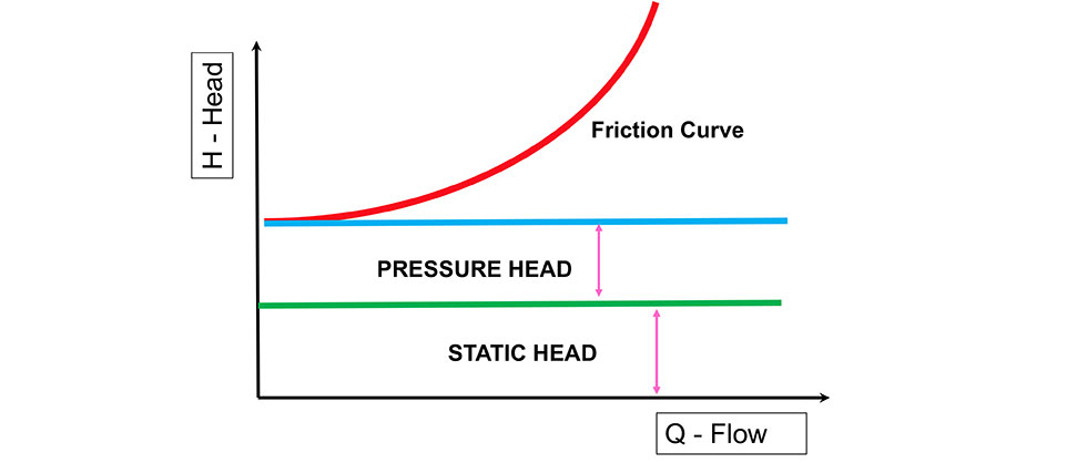
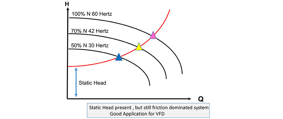
A system curve represents all restrictions, sum of the elevation changes and total friction in the system for the full range of design flow rates. The system resistance curve is comprised of four head factors: static head, pressure head, friction head and velocity head. We can dismiss velocity head due to the miniscule effect.
Static head is the vertical distance that the liquid is required to be moved by the pump. While we are normally concerned with positive static head, it can also be negative (yes, pumping downhill) and these cases can be troublesome because it will move the system friction curve intersection with the pump curve further to the right.
Pressure head is the pressure that the pump has to overcome to move the liquid into a vessel such as a boiler or reactor. The pressure in pounds per square inch (psi) required to overcome the resistance to flow is simply converted to head. Last, but not least, is the friction head. Friction head changes with the flow rate and varies by the square of the liquid velocity (refer to the Darcy-Weisbach formula). Or, simply stated: friction increases exponentially with increasing flow rates.
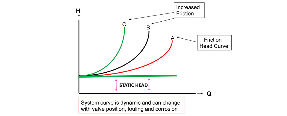
System curves are really not static entities, despite what several calculation and design procedures may have you believe. The levels will change with the process as well as pressure (if applicable) and the friction component will change as control valves change their positions. Further, the system components and piping will become more constricted with age, fouling and corrosion.
The final shape of the system curve will have a big effect on the feasibility and your decision to incorporate a variable frequency drive (VFD). System curves are normally classified as either “friction dominated” or “static head dominated,” but you can also have combinations of both.
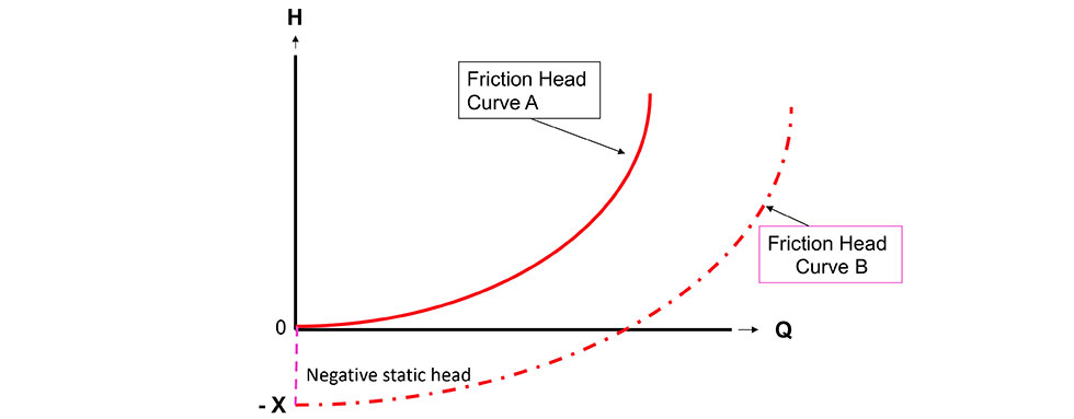
A: No static head and no pressure head
B: Negative static head and no pressure head
Fitting the Pieces Together
VFDs will work well where the pump curve has a rising shape and the system curve is friction-dominated. The flatter the system curve (static head dominated) and the flatter the pump curve, the less effective the VFD system will be. Typically, the steeper the pump curve, the higher the potential for energy savings, but analysis is needed for accuracy. Just because the curve is flat doesn’t mean the return on investment doesn’t work.
Three main categories of systems that may be suitable/applicable to VFDs are:
- constant head with variable flow rate
- constant flow rate with variable head
- variable head with variable flow
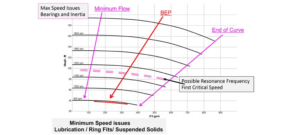
When the system curve is friction-dominated, reducing the speed will cause pump operating points (following the system curve) to follow the best efficiency point (BEP) slope for the pump as power, flow and head also decrease. When the curve is flat (static head dominated), the pump quickly moves out of the BEP and allowable operating range (AOR) as speed is decreased. You can also approach minimum continuous stable flow (MCSF) on the left side of the curve. The boundaries on the right side of the curve are approached quickly in the small operating range afforded.
Potential Issues
For all the pro-VFD folks reading this, please know that I am on your side; I think VFDs are wonderful solutions—most of the time. But it is also important that operators/owners understand that, like all things in the world, nothing is perfect. I suggest all operators, owners and users work with the vendor to avoid these listed issues:
- VFDs are not 100% efficient, so you need to take the VFD efficiency into the overall wire to water efficiency and total cost of ownership (TCO) calculations.
- VFDs may have issues with harmonics, especially on long cable runs. Talk with the OEM about cable length calculations (may require shields) and if a filter addition is required for harmonic issues (manifest as noise and vibrations) that need to be addressed.
- The motor must be rated for the VFD service—most new ones are.
- Depending on the enclosure type and the application (loads that are variable or fixed torque), the motor may have overheating issues due to the lower cooling fan speed as the motor speed diminishes, especially for prolonged periods of low-speed operations. Since most centrifugal pump applications are variable torque and the load diminishes with the speed reduction, the potential for this overheating issue will be lower.
- For motor operations above base speed, the ability to produce sufficient torque is diminished.
- It is better to select a base motor speed and operate in a range at or below that baseline than to continually operate above the baseline speed.
- For motor operations above the baseline speed, consult with the manufacturer and note that 10% over base speed is normally the recommended maximum.
- The motor and pump need to be properly grounded to mitigate issues with induced stray currents. Check the type of bearings and bearing isolators as some styles are worse than others. This applies to both pump and motor.
- Pump rotors may have inertia issues at speeds over the baseline speed. Check with the manufacturer before over-speeding the pump.
- Pump rotors, especially on multistage models, may have a “flexible” rotor design that can create two issues at low speeds.
- Insufficient hydrodynamic pressures at the ring fits and bearing journals due to the reduction of a phenomenon known as the Lomakin effect.
- Many multistage rotors have their first critical speed below the normal operating speed. Check with the manufacturer and program the VFD to pass through and do not dwell in these critical speed zones.
- For pumps on slurry service or suspended solids, calculate and allow for the critical carry velocity of the liquid solids mix. Should the pump slow down too much, the solids will drop from suspension and the resulting blockage can create very dangerous overheating situations leading to ruptured pump casings and flying shrapnel.
- Even at reduced speeds, pumps still have minimum flow boundaries (MCSF). Check with the manufacturer as to the recommended allowable operating range.
- Regardless of speed, the pump still has net positive suction head (NPSH) margin requirements to prevent cavitation.
This column covers only a small portion about drives, motors, pumps, systems and system process controls for variable speed application and economic evaluations. The equipment manufacturers will be a valuable source of additional and pertinent information. I also recommend that you review the guidelines and educational material from the Hydraulic Institute.
