
Third of Six Parts When a system is not working as expected, users and engineers must see the complete picture, especially in wastewater transport systems. While the increasing use of wipes is a challenge, as discussed in Parts 1 and 2 of this series (Pumps & Systems, November, read it here, and December 2015, read it here), different systems will handle this problem differently, and different fluid content will influence performance. Wastewater is not all the same. Depending on the operation or the system's design, the sensitivity can vary for the particular kind of wastewater. Several international initiatives attempt to clarify and define different wastewater. Engineering and planning of wastewater facilities requires knowing what kind of wastewater or sewage must be pumped for trouble-free performance and energy efficiency.
Types of Stations
There are three general types of wastewater pumping stations, depending on pump types used: conventional dry pit pumping stations, submersible pumping stations and submersible pumping stations in dry pit installation. The type that works best depends heavily on the wastewater pumped. Is it a transport station for raw sewage only? Is it a station for stormwater (including surface water)? Is it a combined station for sewage and stormwater? Or is it inside in a wastewater treatment station, which means only pre-screened sewage has to be pumped?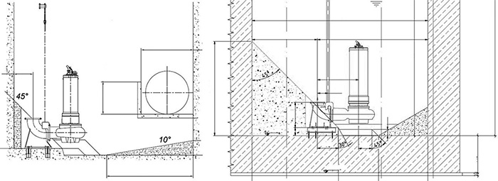 Figures 1 (left) and 2 (right). Two general designs of a submersible pumping station (Images and graphics courtesy of KSB)
Pump Station Designs
The first design aspect to consider is the pump sump and the intake's design. Even if the sewer needs a particular velocity to ensure that all solids can pass, the flow should not be too fast and too hard to create vortex. The inlet can carry a lot of air if it jumps in from a higher head. Engineers must consider these factors. For combined pumping stations that have to pump stormwater and wastewater, a good compromise between minimum velocity to transport all the content and maximum velocity to avoid vortex and entrained air has to be found. If the station only pumps raw sewage, the main risk is a slow flow can cause solids to settle. These stations often run only minutes per day and mostly with low flow. Figure 1 is an example of a stormwater station that has other requirements as a raw sewage station. Even if the stormwater station can handle different solid loads, the operating velocity will be mostly high and it will be flushed during operation. The flow will be much higher and more powerful depending on the particular storm event. Most of these stations will hold back larger material of the heavy loads by a screen before it comes to the pumping stations. The high flow will flush solids and wipes, but high flows can create vortex in the sump and cause unbalanced inflow into the pump's suction. These stations also face higher risk of air drawn into the sump and pump suction. For this reason, the inflow to the sump should not be too high or too close to the pumps. Also, having the inflow below the max water level is a good idea, but engineers must ensure that no backflow can occur. If the intake level is higher than 1 to 1.5 meters (3.3 to 5 feet), a dissipation chamber or "balcony" in front of the intake to the sump is recommended. This feature can contribute to a smaller floor footprint. 1 A dissipation balcony breaks the flow's power to prevent unnecessary vortex and helps to remove air before it enters the pumps. The fillet to the opposite wall should have a slope of approximately 10 degrees. Figure 2 shows a raw sewage pumping station sump. The footprint of the bottom level is much smaller, and the sump, wall and fillets are designed to guide the fluid with the solids and wipes to the suction area. Any area of dead zone would pose a risk of materials settling. The fillets to the wall should have a slope of 45 degrees or up to 60 degrees for heavy cases. A sump designed for raw sewage pumping stations with a larger footprint can cause problems. A growing volume of settling substances may eventually cover the pumps because they do not run often (sometimes just 15 minutes per day), and the raw sewage is thick and dries quickly. If more volume for storage is needed, it is better to use it from the vertical space.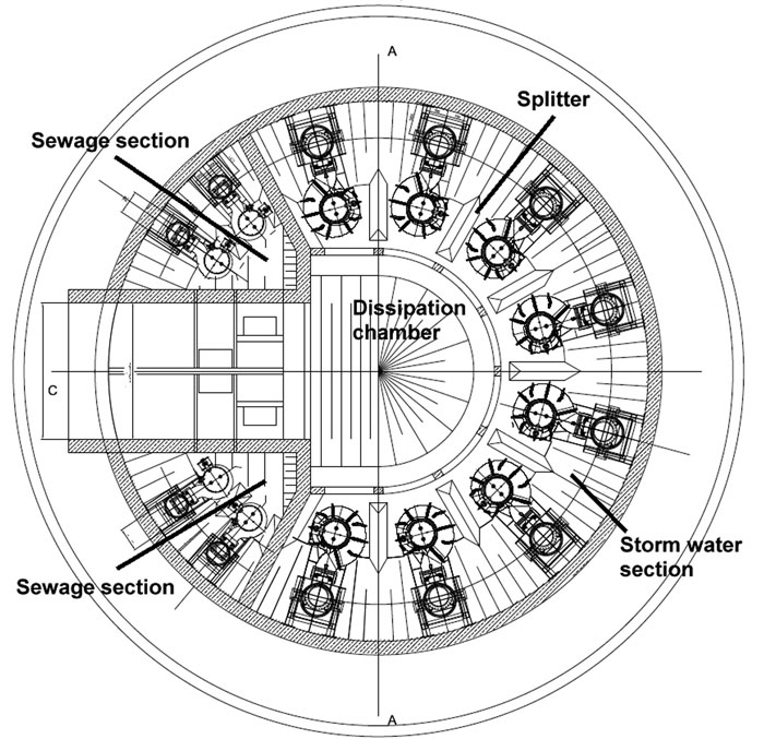 Figure 3. Example of a large combined stormwater and sewage station
.jpg) Image 1. Example of a combined station
Image 1. Example of a combined stationSubmersible Pumping Stations
Sump volume is calculated according to the necessary storage volume of fluid, which is related to the maximum switching frequency. However, dead zones and zones that can cause vortex or swirls should be avoided. It is recommended to have fillets with a slope of approximately 45 degrees, but 60 degrees may be better for heavy loads. The circular sump is typically preferred, but rectangular sumps are possible. Between submersible pumps, splitters are recommended. They are relatively inexpensive and minimize the influence of the flow from the pumps sitting next to each other. Also below the suction of the pump, a splitter can improve the hydraulic flow into the pump and prevent unbalanced load. Proper design and shape of the sump on the pump's backside helps to establish good flow and hydraulic conditions in the sump to improve the transport of solids. For heavy cases and large sumps, a small mixer may be used. Before the pumps start, the mixer can bring everything into suspension and help handle the load in a more homogenized condition. Compared with a valve on a discharge pipe or on a pump with the same purpose, a mixer is more flexible and powerful to flush the sump. A valve is pointed in one direction only and can clog. For stations that have floating sludge on top of the sump level, it is important not to have a constant switch level. It is recommended to pump the sump level down as much as possible. An additional small emptying pump may be helpful. A small mixer in the sump can help to create turbulences and mix the floating sludge with the other pumped medium before pumping.Inflow to the Sump
When possible, the inflow should be below the water level. Often, backflow must be prevented or other geodetic conditions prevent the inflow from being that deep. If the inflow is above the water level, the water jumps into the sump and air can be entrained. For high flows, the available energy in the flow can cause turbulences on any obstruction or the opposite wall. A baffle wall or a dissipation chamber can prevent these effects. They can remove air before it reaches the pumps, reduce the flow's energy and share the total flow between pumps in parallel operation. A dissipation chamber or "balcony" may be needed in cases with an inflow level more than 3.2 feet above the water level.1 Normally, inflow velocity into the sump cannot be defined in a tight limit, but a proven value is an average of 3.3 feet per second.Pipe Work
Because wastewater can change in content and flow over time and different stations handle different wastewater without detailed definition, optimum velocity for wastewater cannot be mathematically defined. However, global wastewater transport experience provides recommended values. Some tolerances are possible depending on load. Especially in the case of VFD operation, engineers and end users must consider minimum velocities. Many breakdowns could be avoided with this consideration. For trouble-free operation, dimensioning and positioning of pipes and valves play an important role (see Image 2 [page 76] and Figures 4 and 5). The right design of piping systems and collecting pipe pieces can help prevent clogging. For parallel operation, single pipes from the pump go up vertically into the bottom side of the collecting pipe. Because not all pumps operate the whole time, there is a risk that solids and other content fall down backward into the single pipe of the pump not operating. If the check valve is not directly below the collecting pipe, the solids settle on the backside of the check valve, preventing it from opening properly.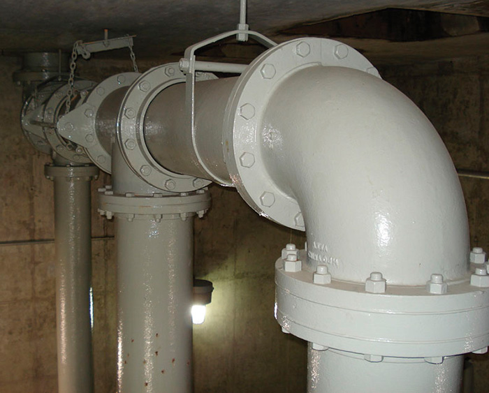 Image 2. A poor example for trouble-free operation
Operating Concepts
If the max flow for a single pump is much higher than the lowest possible flow, as in combined sewage and stormwater stations, stations with jockey pumps will have more stable operation than stations with one size for both conditions. For parallel operation in combination with variable speed, VFD controls need to handle the minimum and maximum flow and velocity.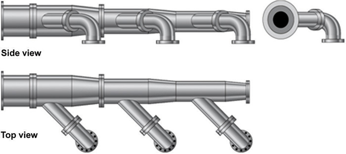 Figure 4. Example of an optimized and proper collecting pipe piece
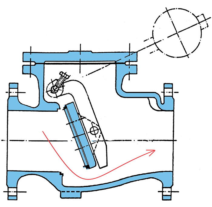 Figure 5. If the selected size of the valve is too large or the variable speed is causing a too low velocity, the check valve will not open fully. Rags and fibers cannot pass through the opening.
Recommendations for Minimum Velocities
These values are good averages for pumping raw sewage.
Inflow into the sump: ~ 3.3 ft/s (1 m/s)
Minimum velocity in the vertical discharge: 4.9 ft/s (1.5 m/s)
Better (for vertical discharge): 6.6 ft/s (2 m/s)
Minimum velocity in the horizontal discharge: 2.6 ft/s (0.8 m/s)
For pre-screened wastewater, the values of the flow velocities in the pipe can be lower. Continuous operation may also influence moderating.
