

During my career, I’ve been involved in designing, operating and maintaining fluid piping systems. My goal was to know how my assigned task fit into the big picture over the life cycle of each system.
All the systems I worked on were expensive to build, operate and maintain. They also were business-critical: their continued operation was vital to the success of the enterprise. As a design engineer, my focus was on selecting the best equipment. During startup and test, my mission was to ensure that the system operated as designed. As a shift supervisor, the goal was to support safe and uninterrupted plant operations. In maintenance, my goal was to identify potential equipment problems prior to failure. In all of these jobs the big picture was the same: to keep the facility in operation to meet the intended purpose.
Most of my past Pumps & Systems articles have dealt with improving systems after performing a system assessment. I’ve written less about system troubleshooting. In the next few articles, though, I want to discuss examples of operational testing to proactively determine the health of a total system. We’ll start this month by focusing on centrifugal pumps.
Finding the Malfunction
All the elements of a system work as part of an interconnected network. For piping systems, the energy balance describes the working of the network. For example, when a pump isn’t operating as designed, it affects both the process and control elements. Most piping systems are designed with enough resilience to minimize disruption, but the longer disruptions go unnoticed, the greater the potential for a forced shutdown.
There are four ways in which centrifugal pumps can no longer operate as originally intended and supplied:
- excessive internal leakage
- changes in the pump impeller
- disruptions in the internal flow passage
- cavitation within the pump
How can we determine if any of these four items are affecting the health of a specific pump in the facility?
The Pump Curve: Key to Spotting Latent Problems
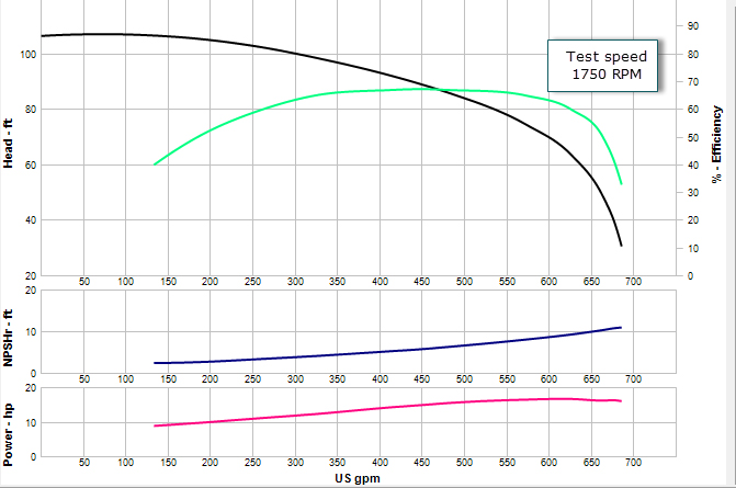
The manufacturer’s pump curve is the key to determining if a pump is operating properly. The curve is created by collecting critical pump operating data—such as suction pressure, discharge pressure, rotational pump speed and power consumed—for a range of expected flow rates. From this data, the performance curve (Image 1) displays the pump’s head, efficiency, power consumed and the net positive suction head required (NPSHr). The manufacturer’s performance curve documents the as-new condition of the supplied pump.
In all pump purchase specifications, users should ask that a performance test be conducted at the manufacturer’s facility, with the user specifying the test standard that it uses: American Petroleum Institute (API)-610, American Society of Mechanical Engineers (ASME) or Hydraulic Institute. It is well worth the additional expense.
If you have not required a performance test, the manufacturer’s catalog curve can help. It may not be a curve of your actual pump, but it provides a good idea of how it should optimally run. A catalog curve represents a compilation of similar pumps of the same size available from the manufacturer. When you order a pump, the manufacturer supplies a catalog curve based on the pump type, size, speed and impeller diameter for use in design calculations.
One final point about manufacturer’s pump curves: unless otherwise specified, all pump test curves use water at ambient temperature as the test fluid.
Designing an Operational Pump Performance Test
Our goal is to develop a pump test that can be performed during normal system operation using installed plant instrumentation that assesses the health of the pump. If the performance test shows the pump is operating on the manufacturer’s pump curve, everything is fine. But if it is not operating on its pump curve, you should investigate and try to identify what may be going wrong.
Here is a seven-step process for developing and conducting an operational pump performance test:
- Obtain the manufacturer’s supplied pump performance curve.
- Describe the test objective and outline the extent of the required results for the test. This can depend on the availability of your plant’s operating instruments.
- Determine the source of the instruments needed to conduct the test. A minimum would be the flow rate through the pump, along with its suction and discharge pressures. You will also need to know the process fluid properties during the test.
- With the system in steady state operations, record the data outlined in Step 3.
- Complete the calculations found on the operational pump performance test.
- Compare the results of the operational performance test with the manufacturer’s supplied pump curve.
If results fall within established guidelines, no further action is needed. If they do not, determine the cause of the deviation.
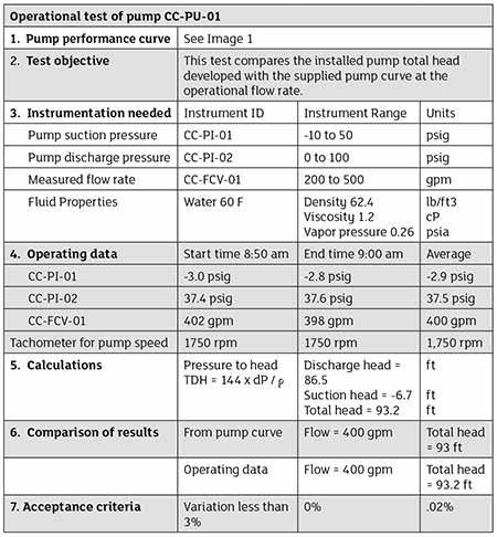 IMAGE 3: A typical example of an operational pump test procedure
Conducting the Test
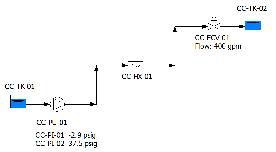
Now let’s set up a performance test for the pump shown in Image 2. This pump moves 400 gallons per minute (gpm) of water at ambient temperature. The installed instrumentation showing pump suction and discharge pressures, along with the flow rate, appear on the diagram. The manufacturer’s supplied pump curve is displayed as Image 1.
A sample operational test of the installed pump CC-PU-01 is described in Image 3. This test outline only compares the pump head as a function of flow rate.
A more comprehensive test could also compare the electrical power supplied to the motor to the shaft horsepower displayed on the manufacturer’s pump curve. The power test crosschecks the results, but it requires the additional expense of a motor power meter.
In this example, the process fluid was water at 60 F and the pump’s operational speed matched the pump test speed. As a result, no changes were required to the pump curve for this comparison.
A change in pump speed would require using the pump affinity rules to determine the pump head. Since the process fluid is water, no viscosity corrections are required. Many pump manufacturers can provide the necessary pump corrections for speed and fluid viscosity. Commercially available fluid piping software can provide the necessary pump corrections as well.
The Best Times to Test
How often should an operational performance test be conducted? I’d recommend a test prior to any planned maintenance outage to determine if the pump should be added to the outage schedule. After conducting pump maintenance, test again to ensure that the pump returns to its as-new condition.
I’d also suggest periodically conducting a baseline operational performance test. The length of time between tests should be commensurate with the importance of the system. Since many facilities have data loggers for plant instruments, this procedure can be performed at any time. Some operators perform daily tests on critical systems.
The Earlier the Diagnosis, the Better
The operational performance test provides a quick check on the health of a centrifugal pump. It is designed to be performed using installed plant instrumentation and should not interfere with any plant operations.
This type of test can also be performed using a digital twin of a piping system. In a future article, I’ll discuss the use of digital twins within fluid piping systems. This technology, along with the industrial internet of things (IIoT), will offer the
ability to perform a variety of real-time operational testing.
Remember: the sooner you can determine if a pump is not operating as designed, the more options you have to determine the best solution. After all, a pump won’t fix itself.
To read more Pump System Improvement columns, click here.
