by Lev Nelik

This article was written in response to the following question from a reader:

Could you explain how an ANSI pump impeller’s clearance setting (both an open-vane impeller with back pump-out vane and a reverse-vane impeller with balancing holes) affects pump performance? What are the advantages and disadvantages of these impeller clearances?

The main reason to use pump-out vanes (POVs) is to change the pump’s axial hydraulic thrust.

In Figure 1, the impeller’s rotation results in dragging into rotation of the fluid in the gap between the impeller and casing walls. This is similar to the motion of a teaspoon in a cup or a disk spinning inside containment. The resulting motion is referred to as forced vortex. This type vortex sets-in in the front and back gaps—between the casing walls and the impeller front (shown on the right) and a back hub (shown on the left). The pressure distribution in the gap is parabolic—higher at the impeller’s outside diameter and gradually reducing toward the shaft center line.

Pressure distribution around the impeller, resulting in axial thrust
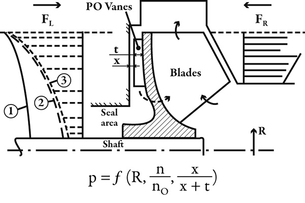
Figure 1. Pressure distribution around the impeller, resulting in axial thrust

Pressure times the area equals force, which is exerted on the impeller from both sides (FR and FL). The difference between these forces is hydraulic axial thrust, which is ultimately transmitted to the bearings and is, ideally, small. This pressure at a given position in a gap depends on the radius, rotational speed of the fluid (divided by the impeller rotational speed) and the gap.

Curve 1 in Figure 1 shows the static pressure distribution behind the impeller hub without the POVs. Basic hydraulics dictate that the faster the fluid moves, the lower the static pressure is. Therefore, if the fluid in the gap could be made to rotate faster, the static pressure would be reduced, and FL would become smaller—closer and, hopefully, equal to FR—to reduce or eliminate the net thrust.

Without a POV, the fluid in the gap is rotated only by the friction (drag) of the impeller hub wall. It rotates with the same speed as the impeller at the impeller wall’s surface (no-slip condition) but is not rotating at the casing wall because that wall is stationary. Therefore, on average, the bulk of the fluid in the gap is spinning at the angular velocity equal to half the angular velocity of the impeller.

However, if the POV is added, the fluid becomes trapped within the POV space and rotates at the same speed as the impeller—at double the speed that the fluid rotates in the absence of the POV. This assumes that the gap between the POV and the casing wall is (theoretically) zero (x = 0). The POVs included do not have to be equal to the number of impeller main blades. However, to simplify the casting production process, they often are.

The liquid gap, x, cannot be zero. Therefore, the actual reduction of the pressure profile (Curve 2) is less—depending on x. If this gap becomes too large, the effect of the POV diminishes and eventually disappears. POVs are most effective when x equals 0 and become completely non-effective when x equals the height of the POVs (t).

The balancing holes are also used to reduce pressure distribution—similar to the POVs. This is why they are called balancing. To be effective, the impeller must have a tight clearance between it and the casing (not shown in Figure 1), to separate the higher pressure zone from the lower pressure zone. The balancing holes connect the back of the impeller with the inlet area, in which pressure is low (close to suction). Some leakage will occur, reducing the efficiency. If there is no clearance, as shown in Figure 1, the leakage will be greater, reducing the efficiency even more.

The POV also reduces the pressure at the mechanical seal area. The vane’s effect can be very strong and sometimes results in creating vacuum and boiling out of the liquid. This can cause problems because mechanical seals do not operate well in a vapor environment.

Regarding performance, thrust balance comes at a cost because the additional power required to spin the liquid faster reduces the efficiency.

This is why higher energy pumps—such as API or boiler feed—rarely have POVs, while ANSI pumps, which are relatively lower horsepower units, have them.

Note that Figure 1 shows an open impeller. The front gap between the impeller and the casing must be tight (typically 0.015 to 0.030 inch, depending on the pump size). Maintaining small front and back gaps—from an efficiency and thrust standpoint—is the challenge. Closed impellers solve this problem but at a reduced ability to handle stringy and fibrous materials.

Another item to consider is a reverse-vane impeller. The impeller shown in Figure 1 is a standard design. To adjust the front clearance, the rotor must be pushed against the casing and then backed-off by the amount of design clearance.

Keeping the casing piped-up is often desired because re-piping it is often an inconvenience. This requires resetting the front gap during maintenance, onsite.

If the impeller is turned around so that the clearance gap is between the impeller and the stuffing box (or sealing chamber), then this clearance can be set at the shop, and the rotor can then simply be brought to a casing and bolted on quickly.

Each design option has advantages and disadvantages, and the ultimate decision remains with a specific application’s requirements.

For more information and additional technical papers on this topic, contact Lev Nelik.