
When designing an application, the design engineer must consider proper bearing lubrication. The lubrication method affects the proper operation of the equipment and the cost of maintaining it. Once the lubrication method is determined, selection of the proper lubricant oil viscosity is vital for prolonging the life of the equipment’s rolling element bearings. Rolling element bearings work best when they operate in a lubrication condition called elastohydrodynamic lubrication (EHL). Bearing life is extended when a rolling element bearing operates with complete separation of the rolling elements from the raceways. Formation of a fully developed EHL layer between the rolling elements and the raceway depends on the speed of rotation, the bearing size and type, and the operating viscosity of the lubricant. Sufficient available oil volume is also necessary for the development of the EHL layer. The film parameter (Λ) evaluates and optimizes this separation given a particular set of application conditions. This article discusses a relatively simple method for calculating the film parameter, with an understanding of the factors that affect it and how to apply it to a design project.
Oil Film Parameter
The EHL oil film parameter, Λ, represents the ratio between the oil film thickness (h) and the surface roughness (σ) (see Equation 1). It is widely used in the study and application of EHL. The raceway surfaces and rolling surfaces of a bearing are very smooth when viewed with the naked eye. However, when viewed through a microscope, the surface profile is not flat. Each surface has a measurable surface roughness that affects the lubrication performance of the bearing.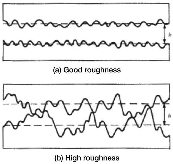 Figure 1. Oil film and surface roughness
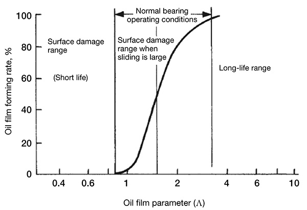 Figure 2. The effect of oil film on bearing performance
Oil Film Parameter Calculation
The Dowson-Higginson minimum oil film thickness equation (see Equation 2) is the thickness at which the rolling element load is highest and the film is thinnest.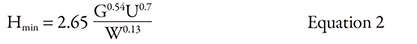 Where:
Hmin = Non-dimensionalized minimum film thickness
G = Non-dimensionalized factor combining material properties and viscosity
U = Non-dimensionalized entrainment velocity
W = Non-dimensionalized rolling element load
Equation 2 can be rewritten by grouping into terms (R) for speed, (A) for viscosity, (F) for load and (J) for bearing technical specifications, and t is a constant.
Λ = t • R • A • F • J Equation 3
Several factors from Equation 3 can be combined. For example, a rolling element load (P) between 98 Newtons (N) (22 pound force—lbf) and 98,000 N (22,000 lbf), F only increases by a factor of 2.54, given that F α P-0.13. Since the P is determined roughly from the bearing size and type, the actual increase in load (F) is more realistically limited to a range of 20 to 30 percent. Since this variation is relatively small in this case, F is grouped together with J (for example, F ≈ F ∙ J), yielding Equation 4.
Λ = T • R • A • D Equation 4
Where:
T = Factor determined by the bearing type
R = Factor related to the rotation speed
A = Factor related to viscosity (viscosity grade α)
D = Factor related to bearing dimensions
Where:
Hmin = Non-dimensionalized minimum film thickness
G = Non-dimensionalized factor combining material properties and viscosity
U = Non-dimensionalized entrainment velocity
W = Non-dimensionalized rolling element load
Equation 2 can be rewritten by grouping into terms (R) for speed, (A) for viscosity, (F) for load and (J) for bearing technical specifications, and t is a constant.
Λ = t • R • A • F • J Equation 3
Several factors from Equation 3 can be combined. For example, a rolling element load (P) between 98 Newtons (N) (22 pound force—lbf) and 98,000 N (22,000 lbf), F only increases by a factor of 2.54, given that F α P-0.13. Since the P is determined roughly from the bearing size and type, the actual increase in load (F) is more realistically limited to a range of 20 to 30 percent. Since this variation is relatively small in this case, F is grouped together with J (for example, F ≈ F ∙ J), yielding Equation 4.
Λ = T • R • A • D Equation 4
Where:
T = Factor determined by the bearing type
R = Factor related to the rotation speed
A = Factor related to viscosity (viscosity grade α)
D = Factor related to bearing dimensions
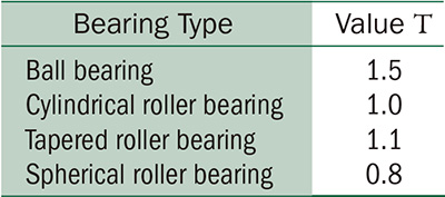 Table 1. Value T
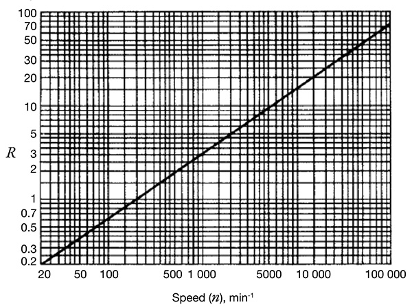 Figure 3. Speed term, R
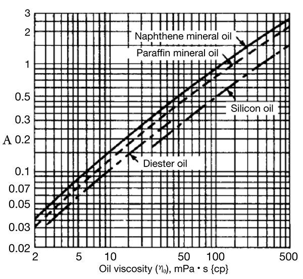 Figure 4. Lubricant viscosity term, A
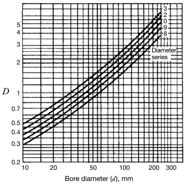 Figure 5. Bearing specifications term, D
Lubricant Starvation & Shearing Heat Generation
The oil film parameter obtained using these calculations is valid when the contact ellipse inlet is fully flooded with oil and the temperature is constant. However, this may not be the case for lubrication during actual operation. If lubricant starvation occurs, the actual oil film parameter value may be smaller than that determined by Equation 4. In this case, the oil film parameter is roughly 50 to 70 percent of that value. The localized temperature rise of the oil at the contact ellipse inlet caused by heavy shearing during high-speed operation will affect the film parameter. This temperature rise causes the viscosity to decrease, with Λ becoming smaller than the isothermal theoretical value. The shearing generation effect was analyzed by Murch and Wilson, who established a reduction factor for the oil film parameter. An approximation, using the viscosity, speed and pitch diameter of the rolling element set (Dpw), is shown in Figure 6.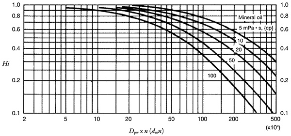 Figure 6. Oil film thickness reduction factor, Hi, because of shearing heat generation