Single-Volute & Double-Volute Casings & Reverse Runaway Speed

Q. What are some differences between single-volute and double-volute casings for rotodynamic centrifugal pumps?

A. The discharge casing serves the following purposes:

  • Collects output from the rotating impeller
  • Decreases the velocity momentum of liquid leaving the impeller before it reaches the next stage impeller or pump discharge
  • Transforms increased kinetic energy of liquid at the impeller outlet into pressure

The single volute is the most common casing style because of the relative ease of manufacture and accessibility for inspection. An impeller discharges into a single spiral-shape passage with one cutwater (tongue) that directs the liquid into the system or into the next stage of a multistage pump. The volute has a constantly increasing area cross section from the tongue, around the casing, to the discharge nozzle. The typical design criteria (see Figure 1.3.3.1) is for the liquid exiting the impeller to maintain either a constant mean velocity, constant velocity momentum or slow slightly through the spiral to the discharge at the design point.

Single-volute casing
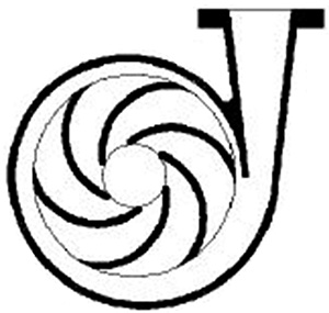
Figure 1.3.3.1. Single-volute casing

Radial thrust on the impeller varies with the rate of flow, being lowest near the best efficiency point (BEP) and higher at reduced or increased flow rates. The thrust at off-BEP operation can be very high for large-diameter impellers producing high head. Radial thrust also varies with impeller diameter, impeller width and total head. Shaft deflection, combined maximum stress and bearing loads must be kept within acceptable limits by different means for best operation.

With a double-volute casing, an impeller discharges into two spiral passages with two cutwaters (tongues). The pumped fluid then discharges via these two passages into a system or into the next stage of a multistage pump. The cutwaters are usually diametrically opposed in the casing. Care must be taken in the design to minimize the loss of pump efficiency. With properly designed passages, radial thrust is minimized, especially at off-BEP flows. The double-volute design (see Figure 1.3.3.2) is typically used to reduce shaft deflections and bearing loads to permit the use of a smaller shaft and bearing sizes or to prolong the life of the pump. The casing complexity is greater than that for a single-volute pump because of the inaccessibility of the outside chamber.

Double-volute casing
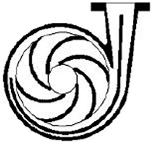
Figure 1.3.3.2. Double-volute casing

For more information about casings for rotodynamic pumps, see ANSI/HI 1.3 Rotodynamic Centrifugal Pumps for Design and Application.

Q. What is reverse runaway speed, and what effects can it have on rotodynamic centrifugal pumps?

A. A sudden power or check valve failure during pump operation against a static head will result in reverse pump rotation. If the pump is driven by a prime mover offering little resistance while running backward, the reverse speed may approach its maximum consistent with zero torque. This speed is called reverse runaway speed. If the head, under which such operation may occur is equal to or greater than that developed by the pump at its BEP during normal operation, then the runaway speed may exceed normal pump operation speeds. This excess speed may impose high mechanical stresses on the rotating parts of the pump and the prime mover. Therefore, knowledge of this speed is essential to safeguard the equipment from possible damage.

The runaway speed is usually expressed as a percentage of speeds during normal operation. In this case, the head consistent with the runaway speed is assumed to be equal to that developed by the pump at its BEP.
The ratio of runaway speed (nro) to normal speed (nno) for single- and double-suction pumps varies with specific speed (see Figure A.10). The data shown should be used as a guide because variations can exist with individual designs.

Reverse runaway speed ratio versus specific speed when the head equals the pump head at BEP
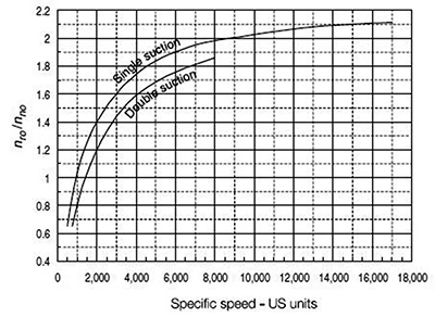
Figure A.10. Reverse runaway speed ratio versus specific speed when the head equals the pump head at BEP
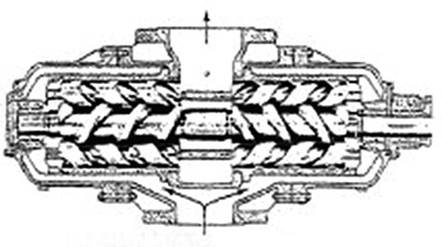
Transient conditions during which runaway speed may occur often result in considerable head variations because of surging in the pressure line. Because most pumps have relatively little inertia, surging can cause rapid speed fluctuations. The runaway speed may, in such a case, be consistent with the highest head resulting from surging. Therefore, knowledge of the surging characteristic of the pipeline is essential for determining the runaway speed, and this is particularly important in case of long lines.

For more information regarding reverse runaway speed with rotodynamic centrifugal pumps, see ANSI/HI 1.4 Rotodynamic Centrifugal Pumps for Manuals Describing Installation, Operation, and Maintenance.

Q. What are the design features of untimed rotary screw pumps, and in what applications can they be used?

A. Screw pumps are used in oilfield, pipeline, refinery, marine, power generation, chemical, hydraulic system and general industrial applications for transfer, lubrication, injection and hydraulics. They handle a wide range of fluids—including fuel oils, lube oils and greases, asphalts, noncorrosive viscous chemicals, and high-pressure coolants.

The untimed rotary screw pump is an axial-flow, multi-rotor, positive displacement design used in many applications for pumping clean to mildly abrasive viscous liquids. It is often a more efficient alternative than centrifugal pumps. The design may use two, three, four or five screws. The most common configuration is the three-screw pump, which consists of a power rotor (drive screw) and two symmetrically opposed idler rotors (driven screws) that mesh within a close-fitting housing forming a succession of cavities to continuously transport fluid to the pump discharge.

Figure 3.1.8.2c

Untimed screw pumps are available with a double-ended flow path (see Figure 3.1.8.2c) or with a single-ended flow path (see Figure 3.1.8.2b). Timing is accomplished through rotor geometry. In a properly applied three-screw pump, no rotor contact occurs because the screws are supported radially in their bores and are hydraulically balanced or free to float on a hydrodynamic film created by the pumped liquid. In other untimed screw pump configurations, the screws may be supported in product-lubricated bushings.

Figure 3.1.8.2b

Units are commercially available in product families with flows up to 1,200 cubic meters per hour (5,300 gallons per minute) and discharge pressures to 310 bar (4,500 psi). Applications cover a wide viscosity range from 2 to 220,000 centistokes (33 to 1,000,000 Saybolt universal seconds) and temperatures from below 0 to 274 C (500 F). Because of the axial movement of the fluid and the compact diameter of the rotors, untimed screw pumps typically operate at two-, four- and six-pole motor speeds. Screw pumps operate with minimum noise, vibration and fluid pulsation. Other important characteristics in many applications are their good suction capability and low shear rate. Untimed screw pumps are frequently found in installations in which extended uninterrupted service life is required.

For more information about rotary pumps, see ANSI/HI 3.1-3.5 Rotary Pumps for Nomenclature, Definitions, Application and Operation.