
One of the claimed advantages of centrifugal pumps over positive displacement pumps is their ability to operate over a wide range of flow rates. Because a centrifugal pump operates at the intersection of the pump curve and the system curve, varying the system curve can easily change the operating point of the pump. The convenience and simplicity of flow control by discharge valve throttling comes at a price because the pump is forced to run either to the left or to the right of its best efficiency point (BEP). However, the real danger of operating the pump too far off-peak comes from suction side considerations: too far to the right, and you risk running out of net positive suction head available (NPSHA ), causing cavitation problems; too far to the left, and flow recirculation at the impeller eye will become evident through noise, vibration and damage. As a result, the flow must be limited on both sides of the BEP.
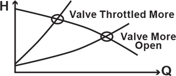 Figure 1. Flow control of the centrifugal pump by the discharge valve (Graphics courtesy of the author)
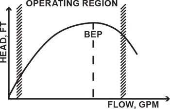 Figure 2. A pump operating range has limits.
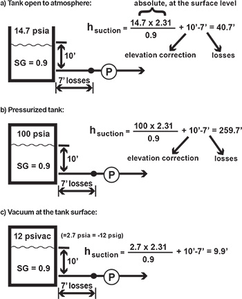 Figure 3a. Open tank Figure 3b. Pressurized tank Figure 3c. Tank under vacuum
Vapor Pressure
Consider the first limitation: high flow. A centrifugal pump stops pumping when liquid turns to vapor. This happens when the pressure somewhere inside the pump drops below the liquid’s vapor pressure. Vapor pressure depends on temperature and a few other factors. Water turns to vapor at 212 F at atmospheric pressure when boiling in an open pot. In a closed pot, the water would reach higher pressure before it boils. Conversely, if the pressure were reduced (vacuum), water would boil at a lower temperature. Water will boil at room temperature if the absolute pressure is less than about 0.4 pounds per square inch absolute (psia). Water has low vapor pressure, but other substances exhibit a very high value. Freon, for example, has a vapor pressure of about 90 psia, and ethane’s vapor pressure is about 700 psi at 80 F.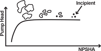 Figure 4. Development of cavitation
 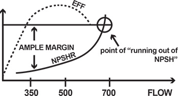 Figure 5. Ample margin of NPSHA is important.
Cavitation
Things are actually happening inside the pump well before the sudden drop of head, though these effects are not obvious. First, at still substantial suction pressure, small bubbles begin to form. This is called incipient cavitation, which can be compared to the tiny bubbles that begin to percolate in a kettle before the water is fully boiling. These small bubbles are formed and collapse at very high frequency and can only be detected by special instrumentation. As pressure continues to decrease, more bubbles form. Eventually, there are so many of them that the pump inlet becomes vapor-locked. This means that no fluid passes through, and the pump stops pumping—the head drops and disappears quickly.NPSH
While it would be ideal to always have enough pressure available at the suction to prevent the formation of bubbles, this is not practical. The Hydraulic Institute (HI) has established a special value of NPSHA at which the pump’s TDH drops by 3 percent. This value at which a pump loses 3 percent TDH over vapor pressure is called net positive suction head required (NPSHR), the value required to maintain 3 percent TDH loss. NPSHR is established by an actual test and may vary from one pump design to another. In contrast, NPSHA is strictly a calculated value of total suction head over vapor pressure. NPSHA must be greater than NPSHR for a pump to reach optimal performance, or to deliver a TDH at a given flow without cavitation or drop in head. When a pump has an obvious NPSH problem, it will stop pumping. However, even small bubbles can cause issues. The evolved bubbles get carried through the impeller passage, at which pressure is rising from inlet to exit of the blade cascade. This increased pressure causes the reverse of what happened to the bubbles earlier when they first formed from liquid particles during phase transformation (boiling). Now, the bubbles are at higher pressure, which squeezes them against the vapor surface tension that maintains them. The bubbles collapse with a sudden inrush of surrounding liquid into a vacuum space previously occupied by the bubbles. The inrush is accompanied by a tremendous, but very localized, pressure shock. If imploded in the vicinity of the impeller blade, this pressure shock would cause a microscopic hammer-like impact, eroding the metal. With enough bubbles and enough time, the impeller vanes could be eroded away, a phenomenon known as cavitation damage. This is why an NPSHA margin (M=NPSHA-NPSHR) is important. The margin is typically 3 to 5 feet, and should be even more, if possible. The NPSHR discussed above was limited to a particular flow on a pump performance curve. At higher flow, the internal fluid velocities are higher. According to Bernoulli, the static pressure (or static head) becomes lower, or closer to vapor pressure. As a result, the static pressure must be increased externally. In other words, a higher value of NPSHR is needed for higher flows (see Figure 5, page 18).Case Study
It is important to specify an ample NPSH margin for a complete range of operation, not just at a single rated flow point. The following example illustrates a common mistake leading to NPSH problems. A pump was procured to deliver between 350 and 500 gallons per minute (gpm), and the manufacturer indicated an NPSHRof 16 feet at 500 gpm. The process later changed, however, so more flow was required—750 gpm. To deliver this increased flow, the discharge valve was opened. At about 700 gpm, however, the NPSHR exceeded the NPSHA at the installation, and the pump began to experience typical NPSH problems—noise, loss of performance and impeller cavitation damage (see Figure 5, page 18). A common method of addressing cavitation resulting from flow-runout operation is to oversize the pump, which causes it to operate to the left of the BEP. In the example above, a larger pump, having the same 16 feet NPSHR but operating at 750 to 800 gpm, would never run out of the NPSHA. It has been common practice to oversize the pump to “make sure” the pump doesn’t experience cavitation. This action, however, often results in other severe problems. When a centrifugal pump operates below a certain flow point, a phenomenon known as flow recirculation occurs in the impeller eye. While it depends on design factors such as suction specific speed, recirculation generally begins between 60 to 80 percent flow and becomes quite severe below 20 to 40 percent. At even lower flows, recirculation may become especially severe, a phenomenon known as surge—a violent, low-frequency sound accompanied by strong low-frequency vibration of the pump and piping (see Figure 6).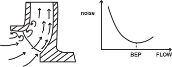 Figure 6. Problems come up when a pump operates at too low flow.