
With today's mandate for reduced fugitive emissions and improved air quality in industrial valves, proper installation of stem packing has become critical. But the importance of effective sealing by packing in the stuffing box goes beyond volatile operations where leakage can be hazardous. It also applies to applications such as steam and low-temperature inert services. Stem packing leakage in non-fugitive emissions applications can be expensive because of product loss and a reduction of operating efficiency. It all comes down to proper installation with precisely the right material. Packing a valve stem requires as little as one or two rings in a rotating stem to as many as seven rings for a rising stem. The rings can be made from braided or a solid die-formed packing. Braided rings need to wrap around a mandrel and be butt-cut or diagonally cut (skive) at 45 degrees. Diagonally cut is the preferred method. It is important that every ring wraps all the way around the mandrel circumference. A variation in ring density will form a leak path.
Compression & Load
The proper technique for valve packing is to seat each ring individually. This procedure eliminates the need to re-pack or re-torque and vastly enhances the life of the seals. For instance, if a user tried to load a set of five rings all at once with a gland follower, the end result would be a lot of compression on top of the ring set and little or no compression on the bottom. In other words, the sealing rings on the bottom are doing nothing to keep the medium from leaking out of the valve. Test data show that a packing set that started with a unit load of 3,500 pounds per square inch (psi) will drop to a load of 2,500 to 3,000 psi within 100 cycles, even when using the proper installation technique. Without proper installation, the compressive load would probably be reduced to 1,500 psi and would no longer be sufficient to ensure sealing.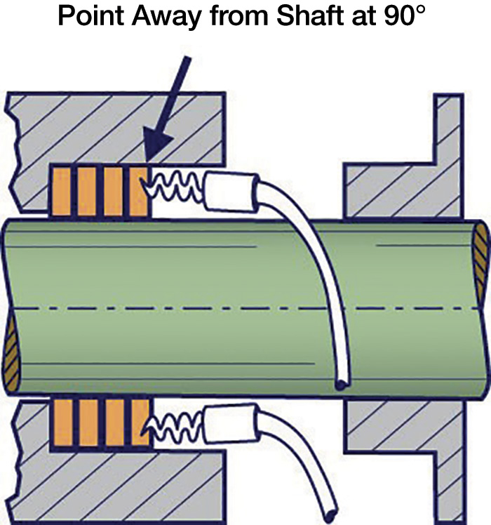 Figure 1. Old packing removal (Image and graphics courtesy of authors)
Temperature Limitations
All materials have temperature parameters within which they work best. For instance, polytetrafluoroethylene (PTFE) is best used when valve temperatures are between minus 150 and 450 F (minus 101 and 232 C). At 662 F (350 C) the material sublimates, which could lead to valve stem corrosion and send toxic fumes through the top of the valve. This is hazardous to plant employees. A seal no longer exists, so the product can escape and cause lost production. The lower limit for flexible graphite, on the other hand, is minus 400 F (minus 240 C) with its upper limit reaching 5,000 F (2,760 C) in non-oxidizing atmospheres. Some flexible graphite manufacturers have enough control over the binder content that the material can reach 850 F (454 C) for fugitive emissions packing and 1,200 F (649 C) for steam service. It can work in all kinds of applications, including some where PTFE is typically used, and flexible graphite is fire-safe for those using media that is combustible.Installation
To properly install valve stem packing, the user must first thoroughly flush the system. This means locking out the motor, closing the valve and relieving all pressure within the valve system. Employees should wear the appropriate safety clothing and eye protection during this process. Some valves only require back-seating. All the old packing must be removed from the stuffing box with a packing removal tool (see Figure 1). Using a mirror, a user should check the stem for pitting or scoring and ensure that the box is clean and that none of the old packing material remains. If necessary, lift the shaft to check the bearings, and replace them as necessary. To determine the correct packing size, measure the diameter of the stem inside the stuffing box. Measure the diameter of the stuffing box bore and the box depth. To get the cross-sectional size, subtract the inside diameter measurement from the outside diameter measurement and divide the difference by two. The packing should be cut on a mandrel of the same size as the stem or using a packing cutting tool (see Figure 3). Do not stretch or flatten the rings. Keep them clean of debris. Never wind the packing into a coil in the stuffing box. Always cut the packing into individual rings using a 45-degree skive or diagonal cut (see Figure 2). Cut each ring and check to make certain that it fits in the stuffing box. Each additional ring should be cut in the same manner. Pre-engineered rings require no cutting.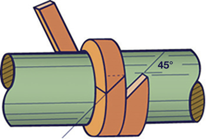 Figure 2. Diagonal or skive cut
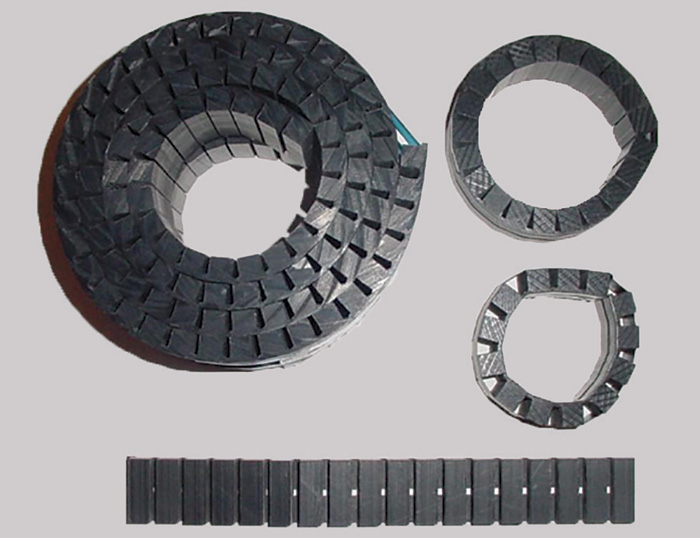 Image 1. Tamping tool
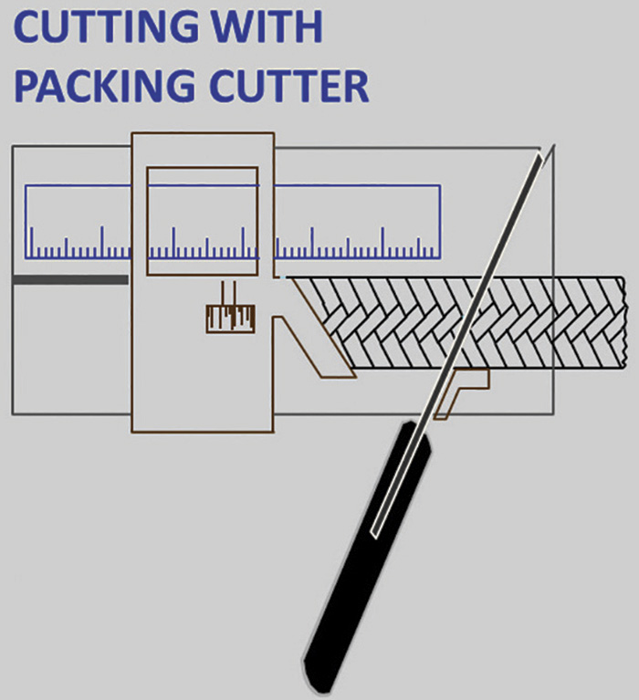 Figure 3. Cutting with packing cutter tool