


Manufacturers have many methods to fine tune or improve the performance of a centrifugal pump. Two of the most common are trimming the impeller and underfiling the discharge vanes.
 Impeller diameter chart
Trimming can help achieve the rated or design point from a pull diameter by reducing capacity and head, which produces a lower capacity and head.
Underfiling is used to improve or increase the head. Sometimes, underfiling is meant to correct an error from overtrimming or to increase head at full diameter.
Impeller Trim
Pumps are each designed for a specific capacity and head. Since a pump cannot be designed for each operating condition required, compromises must be made.
The most common of these is to trim the impeller.
All impellers require a specified trim to achieve the flow and head required for the operating conditions. The trim may be full diameter, an extended diameter (if there is adequate clearance between the impeller and volute), or any size down to the minimum diameter of the impeller.
Affinity Laws
The affinity laws are one of the cornerstones of centrifugal pump performance and understanding them is paramount to understanding how a pump operates. The law is expressed in Equations 1, 2 and 3. These formulas are useful when calculating the head and capacity for variable speed application or for different diameters when the impeller is trimmed.
Equation 1
H2/H1 = (N2/N1)2 * (D2/D1)2
Equation 2
P2/P1 = (N2/N1)3 *(D2/D1)3
Equation 3
Where:
Q = the capacity
H = the head
P = the power
D = the impeller diameter
N = the operating speed
The affinity laws indicate the influence on volume, capacity, head (pressure) and power consumption of a pump where a change in speed of the impeller (revolutions per minute [rpm]) or change in impeller diameter are involved. Note that both a change in diameter or speed have the same relationship to pump capacity. This is because a change in diameter alters the tip speed and the resulting centrifugal force of the impeller in the same way as a change in rpm, therefore producing the same results.
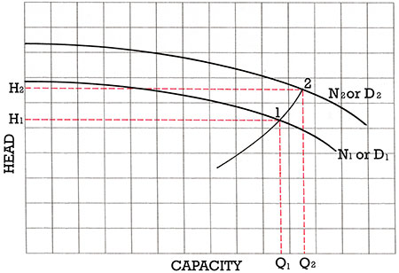
Image 1 illustrates the effect of changing the speed or diameter of an impeller. Note that both the capacity and head change when the speed changes. The capacity by the ratio of the change in speed and head by the square of the change.
Point 2 is generally referred to as the point where the new conditions will pull from, and Point 1 is the desired new operating condition. This would be the traditional impeller trim or reduction in diameter. In cases where the reference curve is smaller than the desired operating conditions, these references are reversed to obtain a larger diameter. This would describe a traditional impeller replacement from D2 where D1 > D2.
Calculating the new diameter is a trial and error process and requires some “Kentucky Windage” (an adjustment to compensate for the circumstance). A point on the performance curve is selected where the new point will pull from (Point 2 in the illustration). Plug this value into the affinity equation and see where Q2, H2 plot on the curve. Repeat the process until Q2 and H2 plot on the reference curve.
The formula used for the calculation is derived from combining Equation 1 and Equation 2.
Equation 4
Where:
H2 = the head on the reference curve the point will pull from
Q2 = the capacity that you think that the new point will pull from
H1 = the new head required
Q1 = the new capacity required
Once H1 is calculated and the point plots on the curve, the affinity trim ratio can be determined by the formula.
In reality, the formula produces only an approximate result as it does not account for the loss of efficiency from moving the impeller away from its ideal position near the cutwater. The results are further corrected using a trim chart.
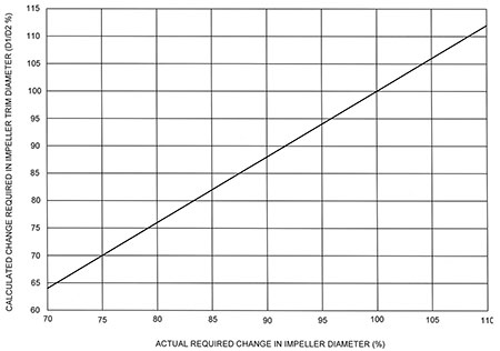 IMAGE 2: Trim chart
The Trim Chart
The affinity laws are used for the initial trim selection and then the affinity diameter is corrected using the trim chart (Image 2). The trim chart produces a conservative value with the results skewed to the high side under the presumption that it is easier to trim the pump again than it is to add diameter back once it has been trimmed.
Equation 5
- If the trim chart diameter is greater than or equal to 97 percent of the reference trim diameter, round the corrected diameter up to the nearest 1/32 inch.
- If the trim chart diameter falls within 95 to 97 percent of the reference trim diameter, add 1/16 inch and round up to the nearest 1/32 inch.
- If the trim chart diameter falls below 95 percent of the reference trim diameter, add 3/32 inch to 1/8 inch and round up to the nearest 1/32 inch.
- For high suction speed (Ns), (> 2,000 US) pumps, apply the above rules and add an additional 1/16 inch to 3/32 inch.
These corrections are just a guide; every pump is different, but it is easier to machine an oversize impeller than to put it back on.
Instead of using the trim chart, the new diameter can be calculated using the slope intercept formula for the line. This formula can be expressed in Equation 6.
Equation 6
Where:
X = the actual trim
Y = the affinity calculated trim
When using the formula in Equation 6, round up to the same amounts as used with the trim chart.
Changes in NPSH
Changes in speed can also affect net positive suction head (NPSH). The new NPSH value can be obtained with the formula in Equation 7. A change in diameter has little effect on NPSH. For speed change up to 20 percent, NPSH can be calculated with the formula in Equation 87. If the speed changes by more than 20 percent, the formula is expressed in Equation 8.
Equation 7
NPSH1 = NPSH2 * (N1/N2)1.5
Equation 8
Note that the formula does not produce exact results. If the NPSH margin is critical, caution should be observed to ensure adequate NPSH results.
Underfiling of Discharge Vanes
Should the head fall below its requirement, small increases, usually around 1.5 percent to 2 percent, can be achieved by underfiling the discharge vanes. Underfiling involves thinning the blades from the back side to a thickness of about 1/8 inch and blending back into the impeller passage as far as practical to a achieve a smooth transition into the original hydraulic contour.
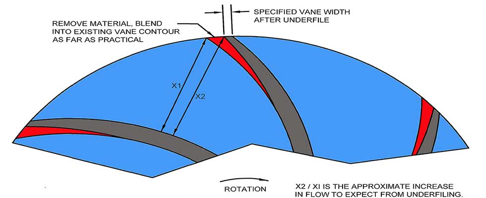 IMAGE 3: Illustration of underfiling discharge vanes to increase the pump size
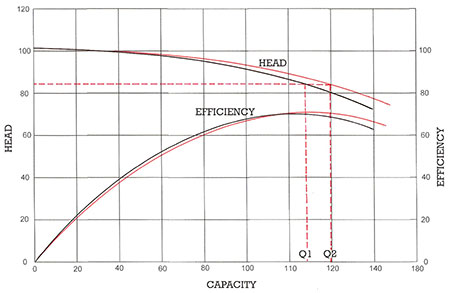 IMAGE 4: Illustration of the increase in capacity and head resulting from underfiling the impeller discharge vanes
There must be no perceivable humps in the transition as noted by running a finger along the hydraulics.
Underfiling opens up the discharge area of the impeller, which increases the impeller capacity. By making the pump larger, the head also increases because the head capacity point at design is moved back on the new curve in respect to the best efficiency point (BEP).
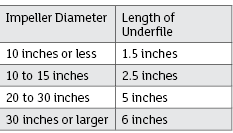
Typical length of metal removal is dependent on impeller size. The numbers presented in the "Impeller Diameter" chart can be used as a guide in determining how far the underfile must extend into the impeller.
The right design point is important for good operation of the pump. An oversized pump must be throttled, resulting in wasted energy plus increased maintenance on the pump and control valve.
An undersized pump will not produce the amount of product needed for the process. Using these methods will help the user fine tune the system for efficient operation.