
Here are some practical insights to prepare, level, install and epoxy grout a pump baseplate.
This June 2004 field study considers our preparation, leveling, installation and epoxy grouting of a baseplate for a boiler feedwater pump and turbine drive system.
Scope of Work Performed
During the first day, we had safety orientation and met with the grouting contractor and company personnel to discuss the work plan. We flipped the baseplate on its side and ground away the paint from the underside of the baseplate top surface for additional bonding of epoxy. We cleaned the foundation top surface, protected the anchor bolts and sealed the bolts with silicone.
On the second day, we tapped the jackscrew bolt holes and protected the anchor bolt threads. We installed neoprene sleeves over the anchor bolts, cleaned the baseplate and the concrete foundation. We set the baseplate on the foundation and leveled it using an optical jig transit.
We covered the baseplate and floor with visqueen on the third day. We also called the pump distributor and sent them the baseplate profile map (as shown in Figure 14). They contacted the local service representative and the service engineer for the pump company.
The missing epoxy hardener came in from the supplier on the fourth day. We poured grout into the baseplate. On the fifth day, we checked the baseplate level with optical alignment equipment.
Observations, Comments, and Supporting Data
To start, the top 1/8-in to 1/4-in of the concrete was chipped away (scarified) so the epoxy would bond to the aggregate, not the sand and portland cement that floated to the top during final floating of the concrete. Figure 1 shows the baseplate and the rigging used to lift and move the baseplate into position.
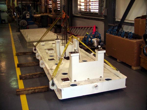
Figure 1. Baseplate and rigging.
We flipped the baseplate over on its side and ground off the paint on the underside of the top plate so the epoxy grout could bond to the metal, not the paint, as shown in Figure 2.
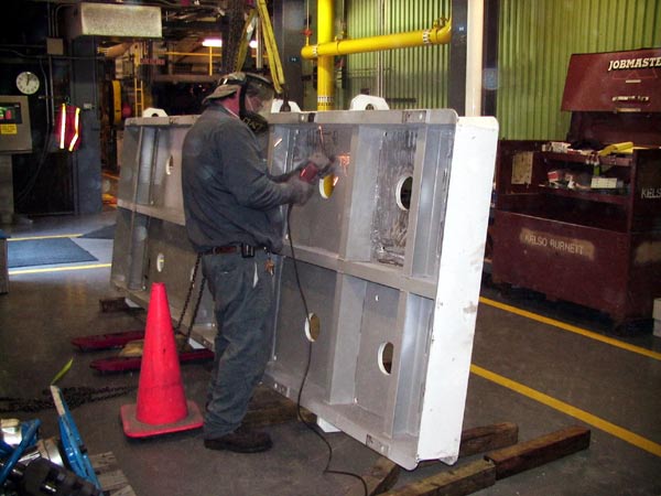
Figure 2. Grinding paint off the underside of the baseplate.
Notice that there are several structural steel cross members placed under each of the pump and turbine mounting feet locations. After removing the paint, any paint dust and metal chips were blown off and the underside of the baseplate was wiped clean with a rag.
Figure 3 shows a bead of silicone sealant being applied to the anchor bolts to prevent the epoxy from flowing into the anchor bolt sleeve imbedded in the concrete.
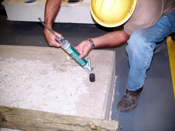
Figure 3. Applying sealant to anchor bolt.
A neoprene sleeve is installed over each anchor bolt to prevent the epoxy grout from adhering to the anchor bolt (Figure 4).
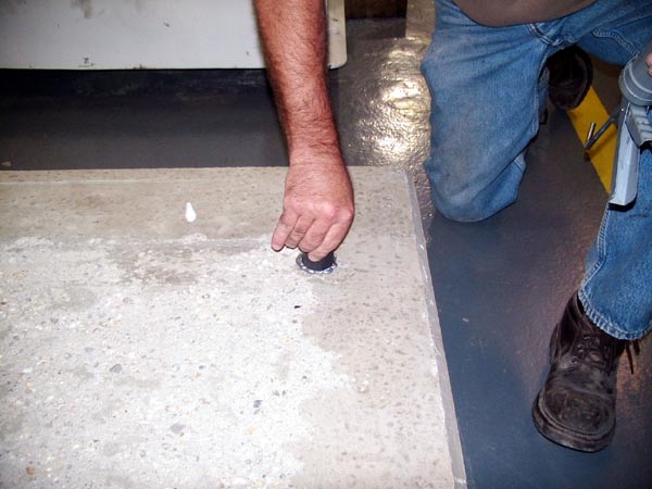
Figure 4. Neoprene sleeve on anchor bolt to prevent from bonding to epoxy grout.
A protective covering was then put onto the anchor bolt threads. The concrete foundation was ready to have the baseplate set onto it. Prior to setting the baseplate, the top surfaces of each foot were cleaned with ScotchBrite™ to remove any rust (Figure 5).
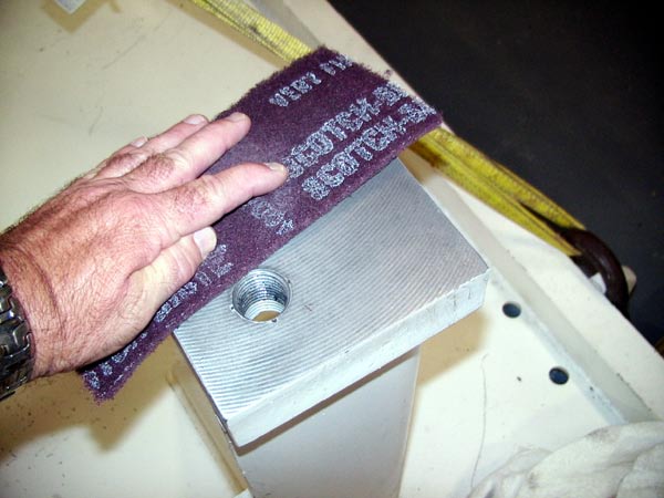
Figure 5. Cleaning the foot pad surfaces.
A fine flat file was then used to remove any burrs on the top surface and bevel the outside edges (Figures 6, 7).
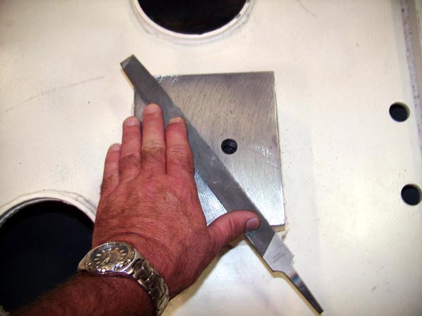
Figure 6. Deburring top surface with a flat tire.
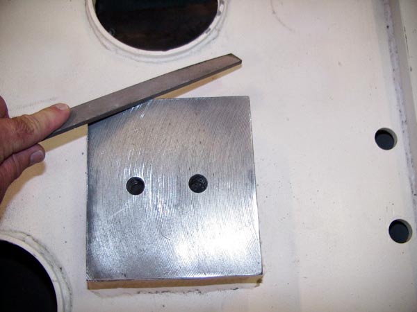
Figure 7. Beveling the edges of the foot pad.
A tap was run through each of the jackscrew holes and an anti-seize compound applied to the jackscrew threads (Figure 8).
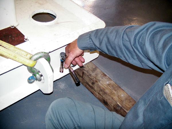
Figure 8. Cleaning the jackscrew threads.
Any dirt and dust was then blown off the top of the baseplate, and the surface wiped clean with a rag. The baseplate was then lifted and carefully positioned over the anchor bolts (Figure 9).
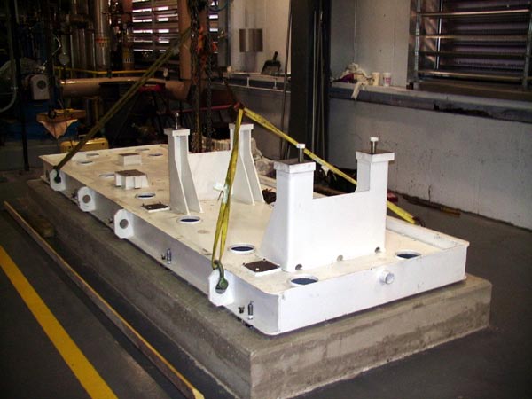
Figure 9. Setting the baseplate into position.
Each jackscrew was set onto stainless steel disks with a “V” coned into the top of each disk for the jackscrew to set into (Figure 10).
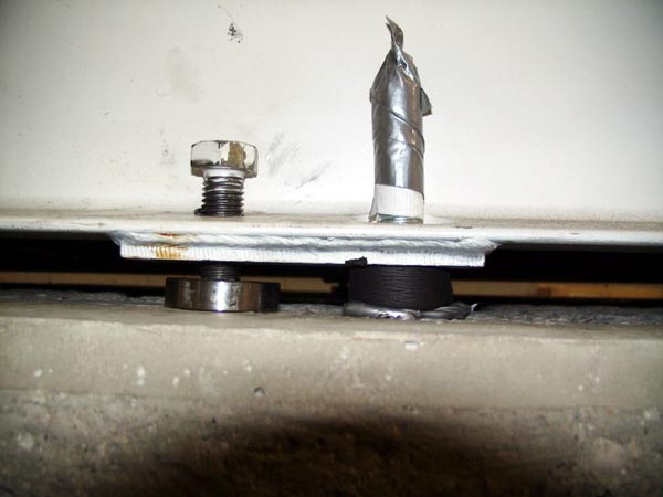
Figure 10. Jackscrew, jackscrew mounting plate and anchor bolt.
A precision machinist’s level was then used to roughly level the baseplate. An optical jig transit was set up and elevations taken on all eight mounting pads (Figures 11 through 13). The line of sight of the jig transit was set slightly above the tops of the pump foot pads so readings could be taken on the 10-in optical scale targets located there. A 20-in scale target was then used on the turbine foot pads since there was a 17-in offset in elevation between the pump foot pads and the turbine foot pads. We decided to set the “shoot for” elevation on the pump pads at 0.800-in and the turbine foot pads at 17.800-in.
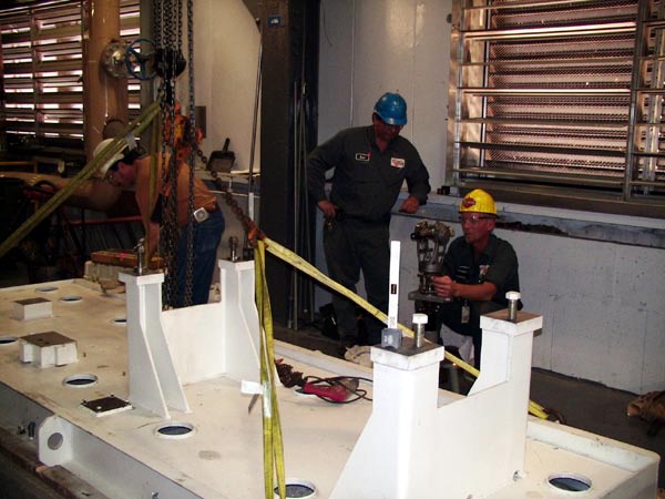
Figure 11. Optical jig transit used for leveling.
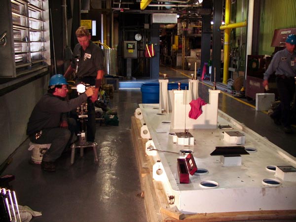
Figure 12. Double checking the elevation.
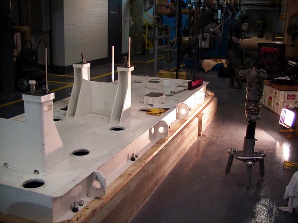
Figure 13. Scale targets on pump and turbine foot pads.
We were unable to level the baseplate by adjusting only the jackscrews. The greatest amount of difficulty in positioning the foot pads at the “shoot for” elevation occurred between the pump pads (B and G) and the turbine pads (C and H).
To position the pads at these locations, we had to distort the baseplate by alternately tightening down on an anchor bolt (i.e. lowering a point), then tightening down an adjacent jackscrew (i.e. to raise a point). At foot pads G and H, the anchor bolts and jackscrews had to be tightened at or slightly over the desired torque values to distort the baseplate enough to achieve the desired elevation. There was no jackscrew or anchor bolt located at pad D to warp the baseplate to get that pad into the desired level plane. Attempts were made to get pad D into the plane using the jackscrews and anchor bolts on the perimeter of the frame, but to no avail.
Once we got close to the desired elevation (i.e. around 5-mils), we noticed inefficiencies. Since we only had one 20-in optical scale target to use at the turbine foot pads, we had to move the scale target from foot pad to foot pad to check the elevation. After moving the optical scale target from pad H to pad D and then back to pad H again, we noticed that the elevations were different without making any adjustments to the anchor bolts or jackscrews. At that point, we decided to take an elevation at one corner of pad H and then move the scale target to another corner of pad H and take the elevation there.
The elevations at the two corners of pad H were not the same. We then realized that the foot pads were welded to the baseplate at an angle (i.e. tilted), which explained why there was an apparent elevation change when the scale target was moved from one foot pad to another. Depending on where the scale target was placed on the surface of the foot pad when it was moved, if the scale target was not placed in exactly the same spot, then the elevation would be different.
We then adjusted the anchor bolts and jackscrews to place the center of each pad as close as possible to the desired elevation. All of the anchor bolt nuts were then firmly tightened to secure the baseplate in its position. We then measured the elevations at the four corners of every foot pad. Figure 14 shows the data collected and the surface profile of the baseplate.
Notice in Figure 14 that none of the foot pads are in the same plane. Pad D is low by an average of 35-mils with respect to the other 3-ft of the turbine. According to API Spec 686 (Recommended Practices for Machinery Installation and Design, Chapter 5) Section 3.9.4.4, the equipment mounting surfaces are to be leveled longitudinally and transversely to within 200-micrometers per meter (0.002-in per foot) for API 610 pumps, and to within 400 micrometers per meter (0.005-in per foot) for general purpose equipment and ASME pumps.
After careful examination of the data in Figure 14, the baseplate profile does not seem to meet this specification. The data was forwarded to the pump and baseplate manufacturer for their review. They were somewhat surprised that none of the foot pads were perfectly level, but particularly alarmed that Pad D was, on average, 35-mils lower than the other 7 pads. Approval was given to go ahead with the grout pour, with the understanding that pad D would have to be shimmed.
Once the baseplate was set in this position, checks were made to determine the final elevation of the pump and turbine centerlines of rotation. According to the drawings, the floor elevation at the baseplate was 65-ft. Using the optical transit and a tape measure, we observed that the floor elevation varied ±1-in, depending on where the measurement was taken around the baseplate. The final centerline of rotation elevation was determined to 68-ft 5.75-in, ±1-in (desired elevation according to drawing was 68-ft 6.75-in).
Calculations for the volume of the baseplate (164-in long, 60-in wide, 7-in deep) were 68,880 cubic in = 40 cubic ft = 1.47 cubic yd. The Masterflow 648CP Plus epoxy grout is sold as a “unit” consisting of one can of resin, one bottle of hardener, and four bags of filler/aggregate. Each unit yields 1.73 cubic ft. Therefore, we needed 23 “units.” Each unit cost $215.95, for a total material cost of $4,966.85.
Final preparations were made prior to the pour. An inventory of the grout material was checked and we discovered we were 4 gallons short of the hardener. The baseplate and a wide area around the foundation was covered with clear plastic sheeting to protect the baseplate and the floor as shown in Figure 15.
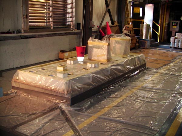
Figure 15. Plastic sheeting to cover and protect baseplate and floor during great pour.
After carefully reading the epoxy grout instructions and the Grouting Checklists in the API 686 specs, we met with the contractor prior to beginning the grout pour. Tasks were divvied up and we determined that the grout would begin to cure somewhere between 60 to 120 minutes after the pour was started, based on the air temperature that day (80-deg F to 90-deg F).
The four bottles of hardener arrived and the pour began in earnest. The procedure was to blend the liquids (epoxy and hardener) for three minutes and then slowly add each bag of aggregate to the mixture. Once the fourth bag of aggregate was added, another two minutes of mixing was suggested before the grout should be poured.
An electric drill with a mixing blade was used to mix the contents. When the first batch was mixed together, it became apparent that the mixture was very viscous (almost like peanut butter). The drill motor quickly became overloaded and the windings began to overheat and smoke. Another drill motor was at hand so the drills were swapped out and, by the second batch, it too became overheated. A larger drill motor was quickly found to handle the mixing, with one batch being mixed at a time. After adding all the contents, the barrel weighed around 250-lb, too heavy for two people to lift and pour directly into the baseplate.
Because of the viscosity of the grout, the most effective way to pour it was by hand, scooping the grout out of the mixing barrel and then pouring it into a hole (Figure 16).
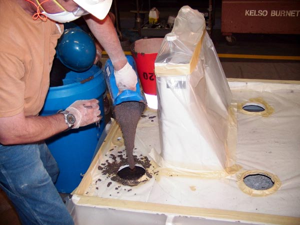
Figure 16. Pouring the grout by hand.
When the barrel was half empty, it became light enough to lift with two people. We then filled up a 5-gal bucket and used it to pour while one or two other people continued to scoop it out with the smaller buckets (which were made with thick, plastic one-gallon laundry detergent containers). Thankfully, two barrels were available, where one crew would pour the grout while another crew would mix the next batch. Initially, each batch took 15 minutes from the time the mix was started to the time the barrel was empty. After a quick calculation, we told the work crew it would take four hours to finish the pour – far in excess of the cure time – so additional personnel were called in to speed up the process.
About the time the fifth batch was poured, the wooden form around the baseplate started to leak (Figure 17).
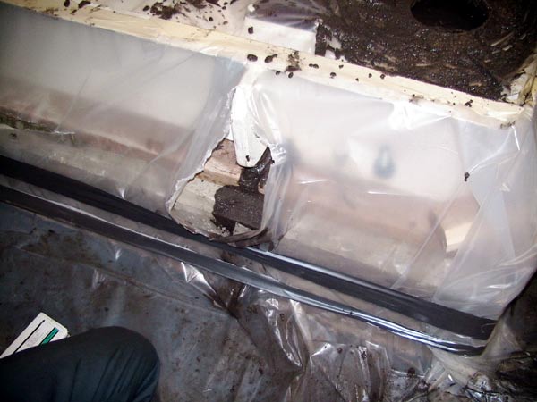
Figure 17. Got a leak!
Thankfully we had the foresight to have some duct sealant at hand in the event that this happened, so the leaks were plugged (Figure 18).
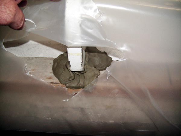
Figure 18. Plugged the leak with duct seal.
It then took approximately 6 minutes for each batch, with bodies scrambling around feverishly mixing and pouring grout until the final batch pour was made.
The top plate of the baseplate was designed with a slope toward the pump side so in the event of a water leak, the water could drain off the base to prevent rust from damaging the baseplate. Knowing this, we started the pour at the low end of the baseplate.
Once the entire baseplate was filled, the grout began to flow and seek its own level. We noticed that the grout began to swell higher in the pour holes at the low end of the baseplate and drop down at the high end (Figure 19).
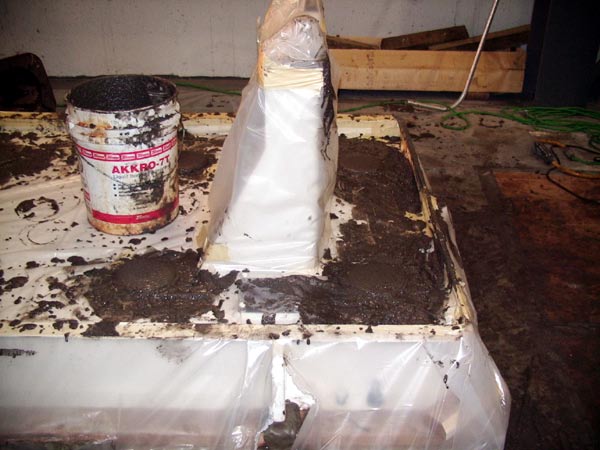
Figure 19. Grout beginning to swell at low end.
As seen in Figure 20, we then topped off the pour holes at the high end, hoping that the epoxy would begin to harden at the low end where the pour first began to prevent it from overflowing onto the top of the baseplate.
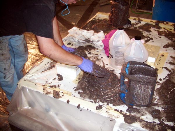
Figure 20. Packing the grout into the pour holes by hand.
The grout did indeed begin to slowly harden and become somewhat like a soft putty, so we began carving off the grout that had leaked out around the form (Figure 21).
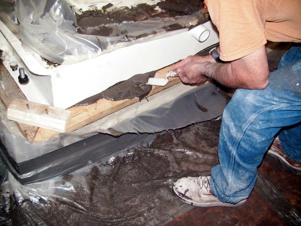
Figure 21. Scraping off the grout where it leaked while still in a plastic state.
Most of the work crew then cleaned up and left. Two of us stayed to smooth off the grout at the pour holes as the grout began to harden – a quickly accelerating process about one hour after the last pour was made. Since the chemical reaction of the epoxy grout is exothermic, the baseplate began to get warm, then somewhat hot.
We noticed that the epoxy began swelling out of all of the pour holes, apparently from expansion of the grout during hardening. Surface temperatures of the baseplate were taken with an infrared pyrometer with temperatures ranging from 127-deg F to 139-deg F. The epoxy soon began to harden very quickly, so we removed the protective plastic sheeting from the top of the baseplate before the epoxy hardened completely. The epoxy had oozed out of the vent holes, so we had to chisel them off as shown in Figure 22.
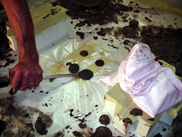
Figure 22. Epoxy now getting hard. A chisel was needed to cut off the overflow around vent holes.
Figure 23 shows the grout pour holes after the epoxy had cured. A fan was placed to begin cooling off the baseplate overnight.
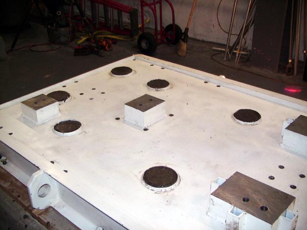
Figure 23. Grout at pour hole after curing.
The next morning we took another set of optical alignment measurements on the eight foot pads to see if the baseplate had stayed in the same position prior to the grout being added. Figure 24 shows the jig transit and optical scale target on the foot pads.
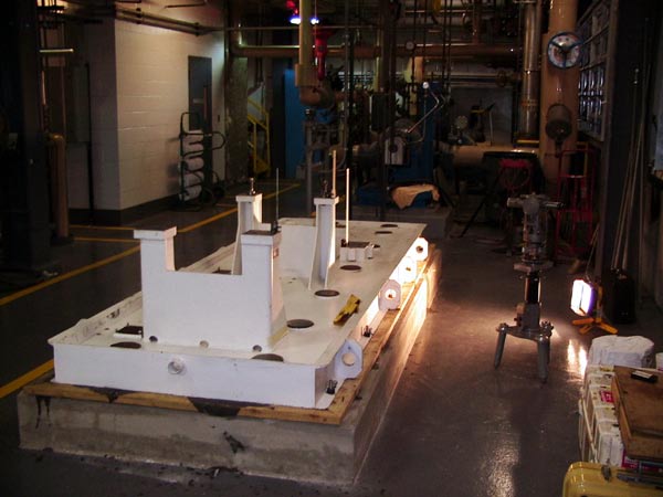
Figure 24. Optical jig transit set back up to check foot pad elevations after grout hardened.
The transit was precision leveled and the line of sight adjusted to buck back into the same elevation plane by observing the adhesive-backed target placed on a nearby building column when the first set of measurements were taken. Figure 25 shows the baseplate profile after the grout had hardened.
Figure 26 shows the baseplate elevation profiles before and after the grout was poured.
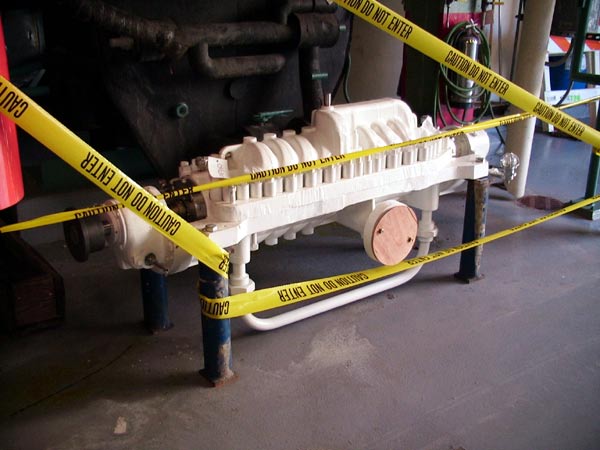
Figure 27. Multistage pump to be installed onto baseplate.
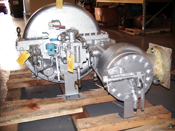
Figure 28. Steam turbine to be installed onto baseplate.
Conclusions and Recommendations
As shown in Figure 26, the baseplate shifted its position after the grout had been poured. Notice that pad E did not change its position very much after the pour had been made. All of the other pads changed their position, with the pads in the center of the baseplate now much lower than either end. The baseplate apparently bowed downwards more in the center, a little at the west end, and virtually none at the east end.
The following conclusions can be made:
- The top surfaces of the four pump foot pads were, and still are not, in the same plane.
- The top surfaces of the four turbine foot pads were, and still are not, in the same plane.
- An 18-in long precision machinist’s level is unable to span across two of the pump or turbine foot pads to check for longitudinal and transverse levelness.
- If a precision machinist’s level had been used, the leveling process would have gone on forever. Depending on which pad the machinist’s level was placed on and what direction it was placed in, the baseplate would have to be re-leveled for each pad. Because of different pad slopes, precisely leveling one pad meant putting another pad out of level.
- Every effort was made to position the pump foot pads and the turbine foot pads in an averaged level, coplanar, and parallel condition prior to grouting. This was achieved on seven of the eight foot pads. This could not have been achieved by the leveling jackscrews alone. In several cases, the anchor bolts nuts had to be tightened to bend the baseplate downward to achieve the desired elevation at certain foot pads. There were no jackscrews or anchor bolts located at pad D to distort the baseplate at that position. All anchor bolt nuts were tightened and the adjacent jackscrews tightened to hold the baseplate in its pre-grouted position.
- Every effort was made to follow the installation guidelines set forth by the equipment manufacturers, the grout manufacturer, and the procedures set forth by API Recommended Practice 686. The objective was to completely fill the baseplate so the grout would bond to the top of the concrete foundation and the underside of the baseplate.
We do not know why the baseplate moved downward. We initially thought that the baseplate may have moved upwards due to the temperature increase from the exothermic reaction of the epoxy. Instead, the opposite happened and it was not a linear move.
We discussed how to “fix” the out-of-level and non-coplanar surfaces of the foot pads now that the baseplate was grouted. First, field machine all of the foot pads to make them level and coplanar. This is indeed possible, but I highly recommend that if this be done, optical alignment equipment be available to assist in periodically measuring the surfaces that would be machined to achieve level, parallel, and coplanar foot pad surfaces.
Nevertheless, in my opinion this would be a waste of time and money. Getting the foot pads flat and in the same plane assumes that the surfaces on the underside of the pump and turbine are flat and in the same plane. Is this true? No data was taken to verify this, despite the doubt of one of the equipment manufacturers. If you study the photograph of the turbine in Figure 28, you will notice that the turbine supports that will touch pads D and E are “L” shaped plates that are axially bolted to the lower turbine casting.
If these bolts are loosened in the casting, it is possible these support plates could be moved due to any clearance between the shank of the bolts and the holes cut into the support plates. API 686 recommends that a precision tilting level and precision scale be used for final leveling of soleplates, but not for baseplates. Nor is any mention made to check for a tilt or twist condition of a soleplate (or baseplate foot) by taking measurements at the four corners of every foot pad.
I have used optical alignment equipment four times to measure the four corners of all the foot pads and seen similar conditions on every baseplate checked this way. I know very few baseplate installations are done with this rigorous measurement process and that carpenter’s levels, not machinist’s levels, are frequently used. Very few people verify that a baseplate is indeed level after the installers say it is. I’m also not sure how often a baseplate was checked for levelness after the grout was poured.
It should now be obvious that this may indeed occur very frequently and that foot pads quite likely have a tilt and or twist condition and the surfaces are not coplanar. Moreover, when the machinery is placed onto the uneven, twisted, tilted foot pads, a flat piece of shim stock will not correct a complex, wedge shaped gap that will occur. It is difficult to fix this, but not impossible.
Finally, what effect will a baseplate that is not level within 2-mils per foot and 5-mils across the entire baseplate have on the successful operation of the machine? If a drive system has a 50-mil slope across the entire baseplate, won’t the thrust bearings be able to accept this slight axial force from gravity? I don’t ascribe to installing baseplates with that radical a slope, but attempting to achieve the tolerances set forth by manufacturers and professional organizations seems to be unachievable in the real world. Many may think that our observations during this particular installation do not occur frequently, but they are probably quite common. Perhaps rethinking soleplate and baseplate installation specifications should be considered.
My final recommendation, therefore, is to install the pump and the turbine, correct the soft foot conditions, align the machinery within acceptable tolerances, perform an off-line to running machinery movement survey to determine how the pump and turbine centerlines move, then readjust the alignment to compensate for this movement if the running alignment is out of tolerance.
A few months after the initial work, the turbine and pump were set onto the baseplate and soft foot checks were made. Figure 29 shows the feeler gauge measurements at all of the foot pads. Notice that only one foot pad on the turbine was making full contact.
This is an excerpt from a forthcoming book, Turvac Engineering Field Service Files. All rights reserved.
Pumps & Systems, October 2006
