


Regardless of the application, most uninterruptible power supply (UPS) users require some degree of customization. It might be as simple as adding an analog meter or two for quick visual reference. Or they may need a full-on tailored system designed to match their unique electrical requirements. Customization is not new to most UPS manufacturers, but few companies go as far as developing an entire new line of products to meet the special needs of a user.
One manufacturer designed solutions for a user's rigorous specifications and ended up with new hardware, software and system design suitable for widespread industry use.
The Problem
Many UPS users operate in unusual and challenging circumstances. Many of their applications are in remote, rugged environments, in hard-to-reach locations away from the populous. While some UPS systems are designed to install in climate-controlled rooms that house electronics and other switchgear, other installations may be exposed to wide temperature swings, humidity and even corrosive environments, resulting in more frequent failures that can be extremely costly.
When a power outage or severe power quality deterioration occurs, pipelines and pumping systems must enter into safe network shutdown procedures. These protocols are conducted by various servers that monitor and control the system parameters. Some users have reported, however, that because of server errors, their systems did not operate correctly even when following the predetermined powering-down protocols.
To remedy this problem, the manufacturer's design engineers conducted a thorough analysis of the reported unsafe network shutdown procedures. They noticed that when the UPS approached the system design life of the backup battery duration and eventual power loss, many of the control systems deployed at a pumping station or pipeline control mechanism malfunctioned. They determined that the malfunction was caused either by the servers not sending the proper shutdown communications before the power loss or sending no communications at all after the power was lost.
The engineers concluded that such a situation is unacceptable because improper sequencing of pump valve shutdown protocols can lead to significant problems such as auto-shutdown valves not activating and, in the worst case, ruptured lines.
The Solution
As a result of their analysis, the engineers determined that the UPS system could monitor the battery time remaining and control server shutdown protocols based on true battery life. A lack of information regarding estimated battery life, however, was responsible for the system errors, causing the servers to lose power before commencing a shutdown of the pump systems. Calculating battery time remaining is essential for creating dynamic protocols for safe shutdown communications from control system servers.
The new software package, which was designed based on these discoveries, allows users to program battery specifications. The system then calculates in real time the estimated battery time remaining during the UPS backup operation (battery discharge cycles). The UPS communicates constantly with all servers in the circuit. If a backup power situation arises, the UPS will determine when—and in what sequence—the servers will power down. The new system also will send shutdown messages to the servers, allowing sufficient time for them to commence safe shutdown procedures and eliminating errors caused by servers simply losing power.
In the fail-safe mode, the new UPS will time out servers based on a predetermined time interval, eliminating any chance of premature server power failure.
Other features include network services over two Ethernet ports and additional functions for the UPS. One of the two Ethernet ports, Network Adapter 1, is on the UPS display board. Network Adapter 2 is mounted inside the UPS.
Network Adapter 1 provides viewing and retrieval of data logs over Ethernet, Modbus TCP messages, and viewing of system parameters and status. The second adapter is for shutting down servers, "heartbeat" messaging from the client running on the servers, testing shutdown from the front panel, synchronization of UPS time to Network Time Protocol (NTP) server, and SNMP messaging.
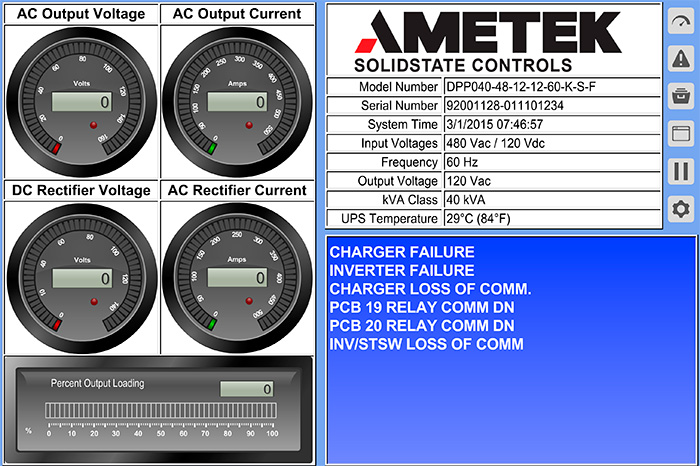 Figure 1. Network Adapter 1 home page
Solving the Primary Problems
In power-loss situations, the primary UPS function is server shutdown. With the new system, this is facilitated by the software running on Network Adapter 2 and additional software running in the background on servers to be shut down. The adapter software sends a shutdown message to a server when the UPS is running on batteries and the shutdown time criteria have been met.
The software's time-out function is also critical. If the communication message sent from the MopUPS software to the Network Adapter 2 is not received after 30 seconds, a server time-out alarm is generated for that server, indicating that communication has been lost with the MopUPS client running on the server. Also, at a time interval specified by the user, the network adapter sends a message to each server expecting a response. If there is no response, the server time-out occurs for the non-responding server.
The new solution also synchronizes both the software on the Network Adapter 2 and the clock on the UPS display board to an NTP server. If communication fails with the NTP server and displays a drift of more than 5 seconds, the time on Network Adapter 2 will be synchronized to the DPP display board, which includes a real-time clock. Once communication has been reestablished with the NTP server, Network Adapter 2 will resynchronize the clock on the display board.
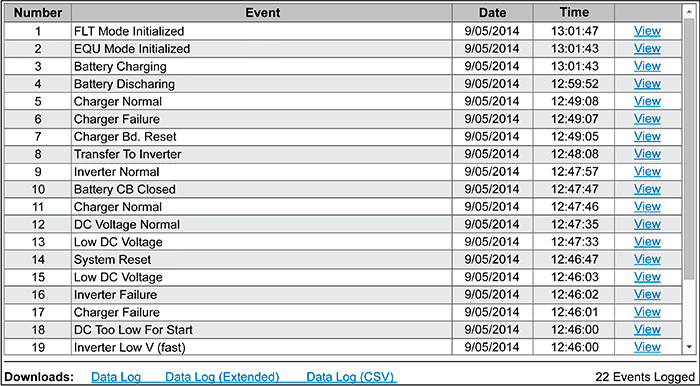 Figure 2. An example of a data log page recorded by the UPS during operation
The web page on Network Adapter 1 allows for monitoring of the current UPS status and the ability to view and download the event, battery history and battery test logs. The home page provides an overall status of UPS operations, an abbreviated alarm status, percent output loading, and UPS manufacturer information. It also provides buttons that will display separate pages for comprehensive measurements, detailed alarms, UPS log and other functions. Values are displayed graphically as meters, along with the actual values for each measurement.
A data log page also gives users the ability to view the data log, battery history, battery test log and the datastore with all events and alarms recorded by the UPS during operation. Once the maximum 2,000 entries have been recorded, the data log will wrap back and write over the oldest entry first.