
Today’s industrial facilities rely on power distribution systems to maintain stable and efficient operation. Plant systems have greater power demands than ever. In most cases where electric installations and devices shut down or malfunction, the problem is thermal. Ultrasonic flow measurement can be used to optimize hydronic cooling of integrated power distribution systems. Ultrasonic meters monitor flow conditions throughout the system and provide data to help determine if fluid volumes are consistent and meet the necessary coolant demand. Increasing awareness of limited energy resources, coupled with the drive to minimize operational costs, has focused attention on energy management. For industrial organizations, enhanced power distribution systems are necessary to keep pace with technology improvements and support a fully integrated solution that maximizes the efficient use of installed power generation. Electrical power is used in every aspect of plant operations. A constant power supply is crucial for plants to operate safely and economically. A shutdown or malfunction of the electrical installation can have major—even catastrophic—repercussions.
.jpg) Image 1. Plants utilize distributed power technologies to ensure a robust energy supply and increase productivity. (Image and graphics courtesy of Badger Meter)
Image 1. Plants utilize distributed power technologies to ensure a robust energy supply and increase productivity. (Image and graphics courtesy of Badger Meter)Need for Effective Cooling
Plants use distributed power technologies to ensure a robust energy supply and increase productivity. However, heat generated by electronic devices and circuitry must be dissipated to improve reliability and prevent premature failure. Traditional techniques for heat dissipation include heat sinks and fans, as well as other forms of automated cooling such as liquid cooling. Hydronic cooling (i.e., the use of water as a heat-transfer medium) is commonly employed to keep plant power systems within the proper temperature range. Water has a high thermal conductivity, meaning it absorbs heat easily—more so than air. It is effective for cooling power supply equipment. Water cooling transfers heat from each part to a radiator that dissipates the heat and cools the liquid—similar to a car’s radiator. In any hydronic cooling application, the liquid medium must flow at designed flow rates within the system. It is also important to assess load variations. Load is calculated by using the flow rate as well as the associated supply and return fluid temperatures. Hydronic cooling systems can be difficult to balance because of the presence of multiple system branches, changes in cooling demand, and pressure differences among the various supply and return lines. Inclusion of balancing valves and flow meters at each terminal or branch circuit facilitates balancing. To help reduce the cooling system’s energy requirements, system designers also seek to minimize the cooling system pressure drop. Measuring the bidirectional flow of liquid circulating in the hydronic system is critical in order to monitor proper cooling performance. Flow measurement instruments are used to detect reduced flow rates, leakage and other conditions affecting the robustness of cooling equipment.Selecting the Right Flow Meter
Companies that design power distribution systems for industrial facilities count on precise flow measurement instrumentation to monitor flow through hydronic system piping and ensure that coolant volumes remain consistent. Flow readings are needed at strategic locations to give a general overview of coolant supply and demand. This often necessitates a non-invasive metering solution that can easily attach to piping to gather flow data without disrupting the system’s configuration and normal operation. Certain flow metering techniques lack the accuracy and/or responsiveness to optimize hydronic cooling operation. Poor meter performance can lead to large fluctuations in the coolant flow rate. This, in turn, results in excessive energy consumption at pumps because of continuous loading and unloading.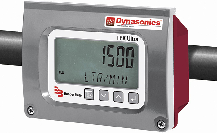 Figure 1. For power distribution system cooling applications, the use of clamp-on ultrasonic flow meters meets crucial accuracy, reliability and cost requirements.
Putting the Solution to Work
For a wide range of power distribution applications, the use of clamp-on, solid-state ultrasonic flow meters meets key accuracy and bidirectional measurement criteria with an installation approach that satisfies cost, reliability and uninterrupted operation needs (see Figure 1).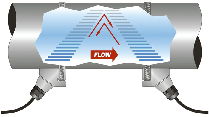 Figure 2. A transit-time ultrasonic meter uses two transducers functioning as both ultrasonic transmitters and receivers.