
Centrifugal pumps are widely used in industrial applications, and pumps absorb nearly a quarter of the electric energy of the European industry. Pumps driven by medium- to low-power motors (70 kilowatts [kW]) represent almost all of the installed machines in oil and gas process plants. Despite the high cost of maintaining pumping systems, control, protection and diagnostic systems for medium- to low-power pumps are not yet widely applied. This type of solution requires external sensors to acquire process parameters, which could have a considerable impact on initial costs. A centrifugal pump model-based control system can solve these challenges by incorporating variable speed drive (VSD) techniques and using installed sensors. Modern control systems change pump rotational speed using frequency converter VSD techniques. Facilities can improve process output and reduce machinery-related production costs with accurate, precise and reliable real-time information about how the machinery works and through congruent control and protective actions. Recent literature discusses many sensorless control techniques, which have a considerable advantage in terms of energy and implementation costs. However, these methods do not allow for simultaneous control of the continuous monitoring system and diagnostics for the equipment. A model-based control system, however, provides the following features:
- an optimal control action on the operational state of the pumping system using a minimum number of field transducers with a consequent reduction of installation costs
- continuous automatic complete pump protection from all possible failure causes through the implementation of a pump performance model
State-of-the-Art Control Techniques
A typical pumping system consists of a driver, a centrifugal pump, valves and tanks. Advanced systems may include a VSD block and sensors that produce the process variable feedback (see Figure 1).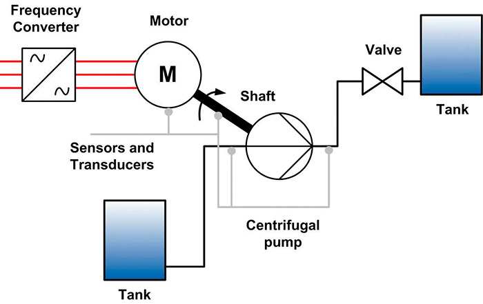 Figure 1. Typical pumping system structure (Graphics courtesy of IPC)
 Pump Model
VSD systems are equipped with powerful control units that enable the monitoring of inverter power output and actual motor speed. The relationship between these variables and the pump process parameters is defined by pump performance curves: flow-head (QH) and flow-power (QP). Both curves are essential parts of the vendor pump documentation. Another relevant system parameter is the net positive suction energy (NPSE) or the net positive suction head (NPSH). The QH and QP curves demonstrate the trend of the head and the pump power consumption against the flow rate, respectively. These correlations are used to determine the flow rate without the need for sensors. For variable speed pumps, manufacturers present pump performance maps as curves plotted for different speeds. Even when only the nominal speed curve is available, it is always possible to determine the operational points at an arbitrary speed using the affinity laws. Further characterization is necessary to perform pump diagnostics. In particular, it is necessary to determine the curves NPSHRQ (NPSHR, NPSH required; Q, volume flow), ηQ (η, efficiency) and PHQ (PH, hydraulic power) that vary with the pump’s speed of rotation.Model-Based Control & Diagnostics
To develop additional diagnostic capabilities, a model-based control system includes a few elementary sensors. Compared with the sensorless version, this choice introduces modest installation costs. The proposed model-based control system uses two pressure transducers installed near the pump flanges and a vibration sensor to perform control tasks and to implement the pump diagnostic feature, respectively.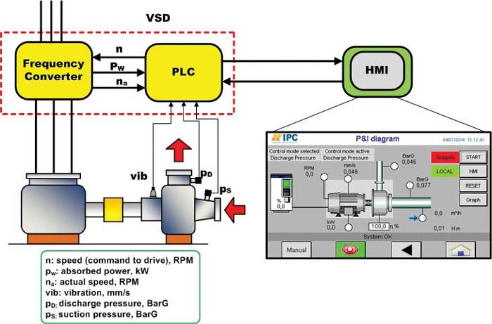 Figure 2. A model-based control system architecture