
API Standard 682 recommends transmitters instead of switches to monitor pump sealing systems.
06/29/2016
Released in May 2014, the fourth edition of the American Petroleum Institute (API) Standard 682 provides guidance for monitoring the sealing systems used on pumps deployed in the petroleum, natural gas, chemical and related industries. Pertaining to pump operations and maintenance, some important aspects of API Standard 682 describe changes in instrumentation used to monitor pump auxiliary seal flush systems. The new edition indicates a preference for continuous measurements using pressure and level transmitters instead of the prior practice of using pressure and level switches.
Pump Problems
Because of the costs associated with monitoring pumps using wired instruments, often only a small percentage of a typical process facility's pumps are monitored online. Many pumps are inspected only periodically by operations or maintenance personnel on field rounds. As a result, the majority of process pumps operate without continuous monitoring, increasing the risk of unanticipated failures, leaks, fires and other potentially dangerous situations. In addition, most pump auxiliary seal flush systems have limited online measurements. Their traditional inspection approach involves manual monthly checks in the field and the use of switches to detect low level, high pressure or high temperature. A traditional mechanical switch is not as effective as a transmitter because it can only provide an on/off signal. Unlike a transmitter, a switch cannot indicate distance from an alarm or set-point, so it cannot be used to predict problems. Most switches do not have onboard diagnostics, making it difficult to know if the switch is operating properly. Smart transmitters allow for calibration, remote configuration and diagnostics, providing additional value and ease of maintenance. Many facilities have limited existing wiring for additional instrumentation, and often implementing a wired monitoring solution is not feasible, especially considering the safety requirements of installing the necessary wiring in an operating process plant. Wireless sensors provide an economically viable option that can be easy and relatively inexpensive to implement.Seal Flush Piping Plans
API Standard 682 defines piping plans and various types of sensors and controls for pump auxiliary seal flush systems. Although the standard defines several plans, the most significant in this context are Plans 52 and 53 A, B and C. These cover dual mechanical seals with a flush fluid for lubrication and cooling. In all plans, heat is removed by cooling water coils in the reservoir or by circulating the flush oil through finned tubes. If an existing facility is upgrading its mechanical seals from single to dual, then it may select either Plan 52 (unpressurized) or one of the three pressurized plans—53 A, B or C—for the auxiliary seal flush system. All four plans need instrumentation to monitor the level, pressure or temperature in the seal flush reservoirs. For existing process units, there may be insufficient spare wires in the vicinity to deliver these measurements to a control room or other location, making wireless sensors an attractive option. The objective of the API Standard 682 committee for the fourth edition was to make recommendations for continuous seal system operation for at least three years (25,000 operating hours). Other objectives were increased availability and simplified maintenance. API Standard 682 gives users several options for selecting instrumentation to achieve these objectives. The current edition gives preference to using indicating transmitters for pressure and level measurements rather than on/off switches. With indicating transmitters, wired instruments or wireless sensors, field personnel can visually monitor operating parameters at the equipment, and operators can view the same data in a control room. Data from transmitters can be analyzed to predict problems before they occur—for example, watching a trend as a measured value approaching an alarm point. Predicting failures allows maintenance to happen prior to a breakdown. For the unpressurized system defined in Plan 52 (see Figure 1), API 682 recommends using pressure and level transmitters. The level transmitter provides a low-level alarm in all cases, and a high-level alarm is specified for cases where the pumped fluid is still in the liquid phase at atmospheric pressure (non-vaporizing).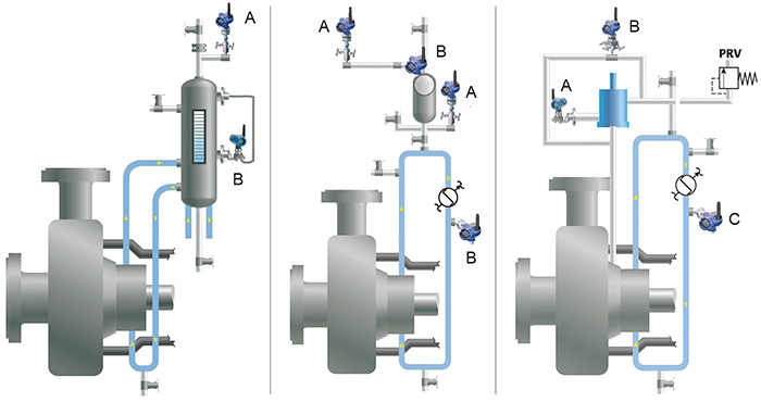 Figure 1 (left). API 682 recommends use of a pressure transmitter (A) and a hydrostatic level transmitter (B) for Plan 52 and 53 A systems.
Figure 2 (middle). For Plan 53 B, API 682 recommends pressure transmitters (A) and temperature transmitters (B) to monitor the circulating flush fluid temperature.
Figure 3 (right). Plan 53 C instrumentation includes a differential level of the piston pressure transmitter (A), a differential pressure flow transmitter to monitor circulating flush fluid (B) and a temperature transmitter (C). (Graphics courtesy of Emerson Process Management)
Figure 1 (left). API 682 recommends use of a pressure transmitter (A) and a hydrostatic level transmitter (B) for Plan 52 and 53 A systems.
Figure 2 (middle). For Plan 53 B, API 682 recommends pressure transmitters (A) and temperature transmitters (B) to monitor the circulating flush fluid temperature.
Figure 3 (right). Plan 53 C instrumentation includes a differential level of the piston pressure transmitter (A), a differential pressure flow transmitter to monitor circulating flush fluid (B) and a temperature transmitter (C). (Graphics courtesy of Emerson Process Management)Wireless Sensors
For many installations, the key to an economical pump seal instrumentation scheme is wireless sensors. Many pumps are located in hazardous areas, difficult-to-reach places or in locations such as wellheads and offshore platforms where electrical power is limited. In many of these cases, using wired transmitters may be too expensive because of the cost to install and maintain the wiring infrastructure. The installation of wireless sensors can be straightforward. The sensor has to be plumbed into the process to measure level, pressure or temperature—no wiring is required. Once the pump seal flush system is equipped with wireless sensors and the accompanying wireless infrastructure, it is relatively easy to add other sensors to a pumping system to measure cavitation, flow, vibration and other parameters such as temperature, strainer plugging, seal fluid level and hydrocarbon leaking (see Figure 4) to provide a comprehensive pump health monitoring system.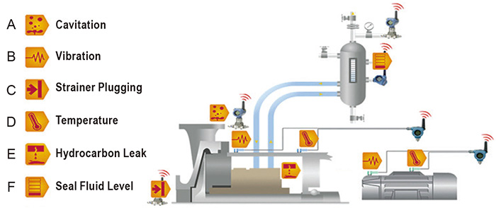 Figure 4: This example of a comprehensive pump health monitoring system uses a wireless pressure transmitter to check cavitation (A), as well as wireless vibration (B), strainer plugging (C), temperature (D), hydrocarbon leak (E) and seal fluid level (F) transmitters