


Part 1 was published in the November 2023 issue of Pumps & Systems.
Motor Circulation Flow Paths
There are a variety of fluid flow paths for circulating fluid through a motor. Most manufacturers adopt those specified in the American Petroleum Institute (API) 685 Sealless Centrifugal Pumps for Petroleum, Petrochemical, and Gas Industry Process Service-Annex D. This standard outlines 14 different flow plans.
Those familiar with mechanical seal plans will be accustomed to this concept. All these plans will not be reviewed in this article, but the most common circulation plans will be discussed. It is not an expectation that the user would identify the model type/circulation plan for their application; this would be done by the manufacturer’s application engineers. However, there are things the user should consider when specifying a canned motor pump (CMP), e.g., availability of cooling water (when pumping a hot liquid) or availability of pipework to route back to a tank (for low-vapor pressure fluids).
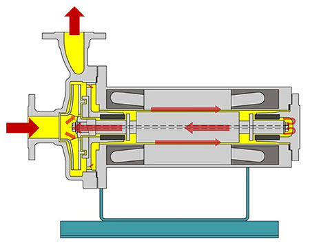
Plan 1-S Internal Circulation (Hollow Shaft)
This is the most common circulation plan and involves a small amount of the pump discharge circulating through orifices in
the pump end (PE) bearing housing and into the motor. It travels through the PE bearing, across the rotor and then
through the cover end (CE) bearing before returning to the suction via the hollow
rotor shaft.
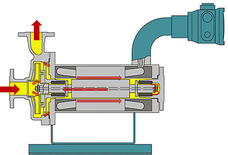
Plan 1-SD Pressurized Circulation
This circulation plan is used for handling volatile fluids with a low boiling point. The premise is the auxiliary impeller adds pressure to the motor cooling fluid to prevent it from vaporizing inside the motor. The flow path starts from the pump discharge and travels through ports to a hole in the hollow shaft.
It travels through the hollow shaft to the eye of the auxiliary impeller. The flow splits and some goes through the CE bearing and back to the auxiliary impeller while the rest travels past the rotor,
through the PE bearings and back to the discharge side.

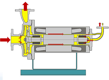
Plan 13-SE Reverse Circulation
This circulation plan is used when pumping fluids with low vapor pressure, e.g., refrigerants, liquefied gases, ammonia, etc. The fluid is circulated only once through the motor to avoid excessive heat pickup in the fluid and cavitation. As discussed previously, any vapor inside the canned motor pump can do significant damage to the bearings and other internal parts.
The flow path is from the pump discharge through holes in the PE bearing housing, through the PE bearing, across the rotor and through the CE bearing before exiting the motor at the cover end. The fluid would typically be returned to a suction tank or collection manifold.
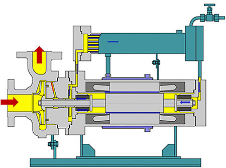
Plan 23-S Externally Cooled Motor
This circulation plan is used when pumping high-temperature liquids, for example, heat transfer oils. This circulation uses a heat exchanger to cool the motor fluid. The same fluid being pumped is used inside the motor, just at a lower temperature. The design uses a thermal barrier to thermally isolate the hot pump end from the cooler motor. This circulation requires site-supplied cooling water or can use an air heat exchanger, although this is less common. Generally, a small amount of fluid circulates from the impeller discharge, through the thermal barrier and toward the heat exchanger process inlet. The motor fluid circulates through the heat exchanger at the PE and then enters the motor at the CE. It passes through the CE bearings, across the rotor and through the PE bearings before repeating this circuit. There is sometimes an auxiliary impeller keyed to the shaft to help circulate the motor fluid. It can be located at either of the bearing housing ends.
Plan 1-S High Temperature No Cooling
Although this uses the same circulation path as highlighted previously, it is worth mentioning as an option for pumping high-temperature fluids when there is no site cooling available. This motor design uses an advanced grade of insulation (class 400) for handling higher temperatures. This motor configuration is typically only available up to 120 horsepower and is often not rewindable.
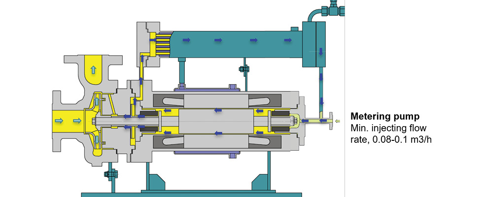
Plan 53-S & 54-S Slurry Handling
This circulation plan is suitable when pumping slurries or abrasive fluids that do not provide good lubrication and cooling to the motor. This plan uses a barrier fluid inside the motor. The barrier fluid is circulated through the motor, either originating from a seal pot (53-S) or an external source (54-S). A labyrinth seal (or internal mechanical seal) separates the pump end from the motor. An external metering pump is commonly used to ensure the motor pressure stays above the pump discharge pressure. The compatibility of the motor fluid and the pumped fluid must be checked, as a small amount will leak from the motor to the pump across the internal labyrinth seal/mechanical seal.
When investigating the use and benefits of a CMP, whether a new installation or a retrofit of an existing pump, it is essential to know the fluid properties and operating conditions. An analysis must include expected abnormal or possible upset conditions, which can affect performance and reliability. This requires a mutual understanding of the application considerations by the system designer, end user and the CMP manufacturer. With this approach, a cost-effective and reliable installation will be realized.
CMPs offer a safe and environmentally friendly pumping option when handling fluids that can harm the environment.
CMP use is rising for these reasons, combined with features that eliminate the most common failure modes for
pumps. Eliminating the mechanical seal, removing the requirement for hot and cold alignment and reducing the number of bearings, plus lubrication systems, can offer a more reliable and maintenance-free pumping solution when correctly applied to the application.