More than ever, commercial building owners and industrial process users need to reduce their maintenance costs and achieve energy savings. Recent innovations in motor and drive technology are making this a reality for commercial and industrial cooling tower applications. A new technology uses a variable frequency drive (VFD) and a low-profile, permanent magnet (PM), direct-drive motor that replaces all the mechanical components—such as gearboxes, drive shafts, disc couplings and existing motors. The removal of these mechanical components also eliminates mechanical energy losses that decrease overall system energy demands. Higher motor efficiency gains are achieved with the PM technology compared to standard induction motor efficiencies found in a traditional system. It is also environmentally friendly because it eliminates the gearbox, which may eventually leak oil into the water, contaminating the environment.
Cooling Tower Technology
To fully appreciate the benefits of this technology, understanding cooling tower applications is necessary. The two types of cooling towers are typically cross-flow towers and counter-flow towers. These are defined by the direction of air passed over the wastewater.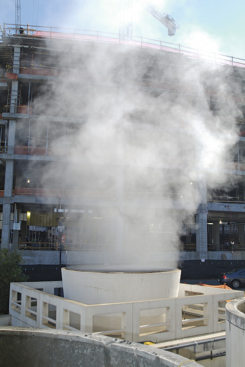 A cooling tower is a structure that extracts waste heat from a process and distributes it to the atmosphere.
Energy Savings Potential
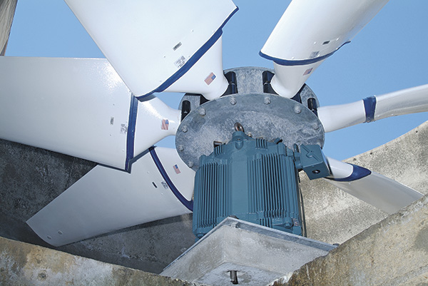
Cooling tower applications follow fan affinity laws which state that horsepower varies by the cube of the fan speed. To put this in perspective, if an application requires a 40 horsepower load at full speed, but the speed could be reduced to 50 percent because of lower heat load requirements, the application needs would only be 5 horsepower or only 12.5 percent of rated full load requirements. This reflects a great reduction of energy consumption. The use of VFDs on new construction has become much more commonplace in recent years because of the energy savings associated with the fan affinity laws. Additionally, most towers being upgraded or refurbished are also being equipped with VFDs. These drives have the advantage of a soft mechanical start, which means no large starting current draw, and they offer the ability to run the fan at any desired speed from zero to the maximum design speed for the application. The energy savings realized by using a VFD are well recognized and documented and have been proven to save between 37 percent and 47 percent in energy costs when compared to applications without VFDs..jpg) A traditional cooling tower fan drive features a right-angle gearbox, which is mounted under the fan and powered by a drive shaft attached to an induction motor. Gearbox failures, oil leaks, failed drive shafts, misaligned drive shafts and excess vibration are all significant problems related to this drive system.
A traditional cooling tower fan drive features a right-angle gearbox, which is mounted under the fan and powered by a drive shaft attached to an induction motor. Gearbox failures, oil leaks, failed drive shafts, misaligned drive shafts and excess vibration are all significant problems related to this drive system.Benefits
Historically, the mechanical components of the fan drive system—specifically the right angle gearbox—have been the largest maintenance issue for cooling tower installations. Gearbox failures, oil leaks, oil contamination, failed drive shafts, misaligned drive shafts and excessive vibration are all significant problems related to this type fan drive system. The features and benefits of the direct-drive cooling tower technology have been field proven and deliver the following advantages:- Significant energy savings
- Soft start capability, which reduces overall tower stress and noise
- Elimination of costly alignment issues
- Removal of high-maintenance mechanical rotating equipment
- Improved system reliability
- System noise reduction
- Decreased yearly maintenance
- Decreased vibration levels
- Elimination of environmental issues, such as leaking oil
 The AC cooling tower direct-drive motor is designed exclusively for the cooling tower industry. The motor combines the technologies of the power-dense, laminated frame motor with high-performance, permanent magnet rotor designs. Combining this motor with a VFD results in a system that is quiet, energy efficient and easy to maintain.