
Over my last 24 articles for Pumps & Systems (see them here), I’ve offered advice solely on centrifugal pumps. This month I’m shaking things up to address progressive cavity pumps (PC), which fit into the rotating positive displacement pump family. Admittedly, I do not have as much experience in this area as I do with centrifugal pumps, but over the last 13 years I have seen the same mistakes made repeatedly, resulting in expensive damages.
The basic working principle of operation is a rotor (usually made of solid metal) shaped as a single helix rotating inside a stator (usually made of an elastomer) that has a double helix cavity. The concept seems complex, but once you visualize how it works the simplicity and the beauty of the design is clear.
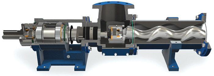 A cutaway of a progressive cavity pump (Courtesy of the author)
The pump is covered under International Organization for Standardization (ISO) standard 15136.1 for petroleum and drilled down-hole applications. Specification American Petroleum Institution 676 also covers the pump in petroleum applications, otherwise the PC pump is covered under American National Standards Institute (ANSI) 3.1- 3.5 for rotary positive displacement (PD) pumps. This type of pump is classified as a rotary PD pump by the Hydraulic Institute.
The PC pump is often maligned as the pump of last resort. However, the PC pump is an excellent choice as the fluid viscosity increases beyond the efficient range of centrifugal pumps.
It is also very useful in applications where the fluid is abrasive and/or shear sensitive. In agricultural applications the pump is used to move fruits or berries with little to no harmful effects to the product.
Selection Process
The more you know about the fluid, the better you can match pump size, operating speed and material for a cost effective and reliable application.
As a rule of thumb, the PC pump is an efficient selection when the pressure required is higher than the flow rate (PSI > GPM). It is prudent to address the major concerns in the selection process: abrasion, temperature and viscosity.
Wear is proportional to speed, more so in a PC pump than a centrifugal pump. As the viscosity of the fluid increases, you should reduce the speed of the pump. As an example, with a fluid viscosity of 1000 centipoise (cP) the speed should be somewhere around 150 rpm, but at a reduced viscosity of 100 cP the speed could be raised to 700 rpm.
The higher the abrasive properties of the fluid the better to select a larger pump and run it slower than a smaller and faster pump. Yes, the larger pump will initially be more expensive, but the choice will pay off quickly with an excellent return on investment. The smaller and faster pump will become a “money pit” of parts and maintenance.
For improved wear resistance, chose a design to keep the linear fluid velocity less than seven feet per second, but realize that solids can fall out of suspension at velocities less than four feet per second.
You should reduce the pressure per stage if the fluid is abrasive. If the fluid is not abrasive you may elect to achieve 85 psi or more per stage, but as abrasiveness increases you should reduce the pressure per stage to as low as 20 psi. Most manufacturers limit the pressure per stage to under 90 psi with an elastomer stator. There are some exceptions at higher pressures. High viscous fluids with low abrasive properties and a rigid stator can be as high as 250 psi per stage.
A rigid stator is not made from elastomeric materials; it is metal and the fits are not interfering. Rigid stators are sometimes used where viscosities exceed 2000 cP and elastometer temperature limits are exceeded.
Consider Heat
Temperature has a direct effect on the resiliency of the stator elastomer, so the stator material should be matched for the temperature. Elastomers expand at a much faster rate than metals, usually as much as 10 times faster.
The elastomer stator will expand as fluid temperatures increase, but since the outside diameter is restricted by the heavy shell/metal casing the growth is essentially unidirectional inward. The pumping cavity becomes smaller and contacts (engages) the rotor even tighter. What was perhaps a zero or slight transition fit will now become a tight interference fit, sometimes to the point of destroying the stator. (You can smell the rubber burning at that point.)
Stators start thermal expansion in the 70–130 F degree range. It’s important to note they will shrink (contract) in the 50 F degree and below range, when double chromed rotors may increase the fit interference. If you know the range of the fluid temperatures, then you, in conjunction with the manufacturer, can customize your stator and rotor dimensions to yield the best performance and reliability. There will also be temperature multipliers in the design horsepower calculations. Note that some manufacturers offer a thin wall stator to mitigate the effects for this reason.
Consider the fluid properties in relation to the chemical resistance of the stator in your selection process.
Rotors are typically 4140 tool or 316-SS austenitic steel that is chrome plated, but they can also have chrome oxide, carbide and ceramic coatings. The rotor will usually be solid metal, but some manufacturers also offer hollow steel as a weight (mass) reduction feature in larger rotors.
The pump portion of the unit may be able to pump the fluid, but the drive components may not be able to handle the required horsepower/torque. Consult with the OEM on the drive limits. Multiple PC pumps can be used in parallel for increased flow rates.
Tips for Reliable Operation & Reduced Maintenance
- Stators will usually wear out first. Replace the rotor for every two stators replaced on a pump.
- Used stators can often be reversed (flipped end for end) and reused.
- Check the instruction manual for how to measure wear on the rotor and what the limits are. Check wear at the proper intervals and you can save the cost of a new rotor.
- If rotor wear is caught before the chrome plating is removed they can be re-chromed.
- Rotors worn past the chrome plating need to be replaced.
- It is rare for the rotor to be bent.
- Stators that are pitted, gouged or worn must be replaced.
- Use a non-petroleum based lubricant when installing the rotors into the stators to preclude an elastomer attack and the resulting swelling. Castor oil is inexpensive and works great. Note: If the pump is food- or pharmaceutical-grade there may be restrictive and special requirements for lubricants, especially in contact with the fluid.
- Do not over-torque the foot bolts around the stator as this can put the pump in a bind.
- Flush product out of the pump while it is still in place to allow for easier and cleaner maintenance. Cover the suction and discharge flanges/opening to keep out foreign objects. Make notes of connections and orientations. Pictures are valuable tools in this case.
Stators are like red wine, you need to protect them in storage if you want to keep them in proper condition. Heat and humidity are an enemy of rubber stators. UV light and ozone are like kryptonite to the elastomer materials and will destroy the stators. To reduce exposure, place protective caps on the ends of the stators. If your spare stators are older than three to five years you can expect some deterioration in quality and consequently operational life.
Purchase your spare and replacement rotors and stators from the same manufacturer. Each manufacturer has different specifications, dimensions and tolerances that are ever so slight, but it will make a big difference when operating in the unit. A rotor from one source may not perform as well in a stator from a different source or vice versa.
For more Common Pumping Mistakes columns, click here.
Progressive Cavity Pumps
Advantages:
- Good for solids handling and can also handle air entrained, multiphase and abrasive liquids
- Excellent choice for high viscosity applications
- Offer low net positive suction head required
- Excellent self-primer pump
- Do not vapor lock
- Offer high accuracy as a metering pump
- A given size/model of pump installation will handle a wide range of viscosities very well
- Reversible direction/ bi-directionally. The pump can be operated in either direction, and the suction becomes the discharge and vice versa
- Can be operated vertically
- Quiet operation
Disadvantages
- Due to the interference fit between the stator and rotor, a fluid film is required to lubricate the sliding (contacting) surfaces. Running the pump dry is by far the biggest reason these pumps fail.
- Low speed also requires VFD (variable frequency drives) and or gear reducers that add to the cost of the installation. (These pumps are great at self-priming, but the rotor stator fit has to be lubricated in the process.)
- Low speed also translates to low flow, which can be a disadvantage in many applications.
- Flowrate and energy required to get the fluids to the pump will require technical review. With highly viscous fluids there is a pump speed above which the fluid will not flow fast enough into the pump. When this occurs, the volumetric efficiency of the pump is compromised. The manufacturer can assist in determining the speed limits for a given fluid and viscosity.
- Possible high startup torques can require drivers (motors) to be larger than would otherwise be required. The running horsepower may only be half of the required startup horsepower.
- Can only pump a limited distance. Generally, the distance to one foot of discharge piping to one PSI of pressure developed. For longer distances consult with your manufacturer.
- Low viscosity fluids tend to slip by the rotor to stator fits and the pump will be less efficient.
