
In recent years, most industry professionals have been leaving the decision of driver size selection to pump-selection software. There is nothing wrong with that choice, and many selection software programs do a great job. This column will explore some of the specifications and decision-making processes that occur behind the scenes. I offer this information because I have witnessed several poor decisions in recent years with regards to driver selection and sizing. It is a delicate balancing act fraught with compromises to properly size a motor as a pump driver. Too big and you waste money in the initial cost and over the life of the unit because it manifests as inefficiency. Too small and you will reduce the life of the motor. Overloaded motors will run hot and fail the insulation system. Just an 18 degree Fahrenheit increase in normal winding temperatures will reduce the insulation life by 50 percent. In most cases the pump driver will be an alternating current (AC) electric induction motor or an internal combustion engine. When quality steam is available and the duty cycle is approaching 100 percent, turbines are an efficient driver choice, especially in the larger horsepower (HP) ranges above standard National Electrical Manufacturers Association (NEMA) frame sizes.
Making a Choice
Let’s start with a simple pump curve and select the correct driver based on the rated hydraulic conditions. Refer to the pump curve (Figure 1, page 23). The rated hydraulic conditions for the example pump are 270 gallons per minute (gpm) at 115 feet of total dynamic head (TDH) pumping clear water at an ambient temperature of 68 F with a specific gravity of 1.0 and viscosity of 1 centipoise. Unless the curve states otherwise, most every pump performance curve is based on clean water at 60 or 68 F with a 1.0 specific gravity and a viscosity below 5 centipoise. The example pump is an end suction American National Standards Institute (ANSI) pump of size 2 x 3 x 6 operating at 3,550 rpm with the impeller trimmed to 5.5 inches. I have simplified the curve as much as possible for this example (efficiency at the duty point is 77 percent). Note that the pump will require 10.2 brake horsepower (BHP) at the duty point also known as the rated point. I used the basic horsepower formula (see Equation 1) to arrive at that number, which corresponds with the selection software. The program selects a 20 HP motor for the condition because I have the software sizing criteria set to select a motor for the maximum power on the design curve (an industry best practice).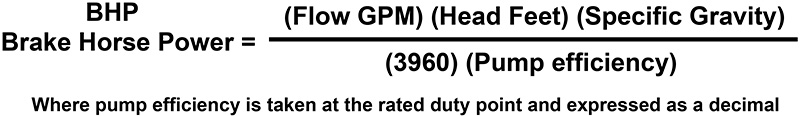
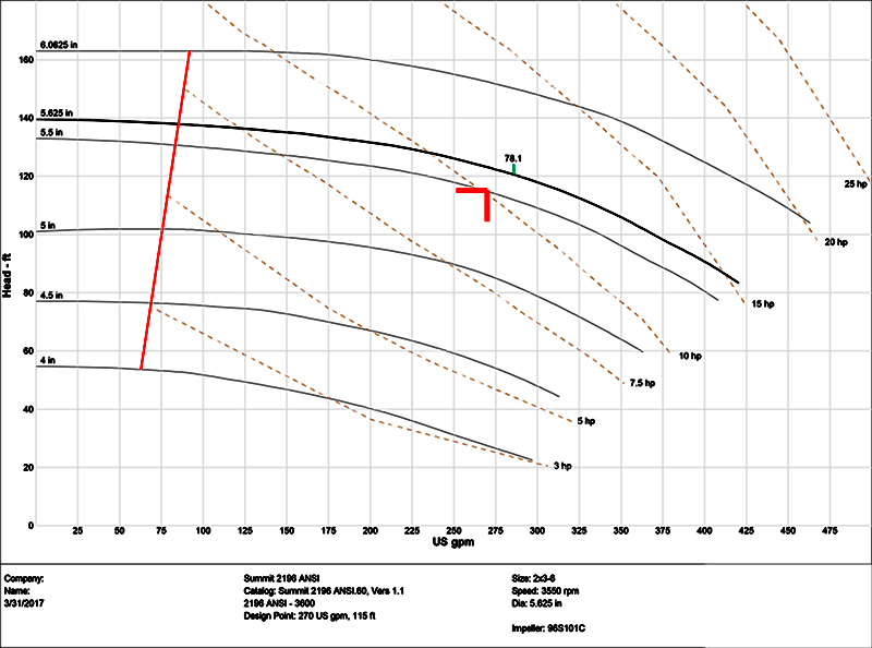 Figure 1. Pump curve (Courtesy of the author)
Possible Changes
Remember that in the example, the fluid was clean water at 68 F and 270 GPM at 155 feet (TDH). Now suppose the fluid properties have changed to a higher specific gravity of 1.2. This realistic and simple increase will change the required HP from 10.2 to 12.22 for the same head and flow. For a runout condition (far right on the curve) on the same size impeller of 395 GPM at 82 feet the new required horsepower will exceed 15 HP. This, by convention, now dictates a 20 HP motor. The point of the example is to illustrate that changes in the specific gravity will change driver size for the pump. Make your decisions accordingly. Another practical example would be a change in viscosity. The first example was based on water with the viscosity at 1 centipoise. It is very common to have fluids that have much higher viscosities. Also note that the viscosity will change directly with temperature. A simple viscosity increase from one to 50 centipoise will increase the required horsepower from 10.2 to 13, and the revised maximum for a runout condition will be almost 23 HP. Consequently, the required motor size is now 25 HP. Most experienced pump people will, as an accepted best practice, size the motor driver to be non-overloading for the selected impeller diameter curve. Many industries and end users will specify that the motor be sized to be non-overloading for the maximum size impeller in that pump (6.0 inches in our example), and in many cases there will be a service factor that is added to that max impeller quantity or at least to the selected impeller requirement. In American Petroleum Industry (API) applications and specifications there will be a service factor added to the motor size once the base size is selected (not to be confused with the actual motor service factor from the manufacturer). Sometimes there are cases that require a size that is obviously too large, and documented exceptions are made to reduce the motor by one size. For motors 25 HP and under, the factor is 1.25. For motors 30 to 75 HP, the factor is 1.15. For motors 100 HP and larger, the factor is 1.1. Another factor to take into consideration is the specific speed (NS) of the pump impeller. At the lower and mid-range specific speeds a pump will require more BHP as the flow is increased. BHP starts at a low number and increases as the flow increases. For high NS pumps (axial flow in the ranges above NS of 6,000) the BHP is high at the low flows and actually reduces as the flow increases. This could be a topic for another column, and it is not my intent to explain further here. The point is that the motor size needs to be carefully selected and is the main reason why these high NS pumps are started with the discharge valve open in lieu of closed. Otherwise the motor would trip on overload, unless it was oversized.Internal Combustion Drivers
A few comments about internal combustion drivers: Simply stated, engines do not handle and react to torque load requirements similarly to most induction motors, so they must be oversized for the service. Otherwise, the pump will not run at the correct speed or at all. Additionally, electric motors run very efficiently near full load while air-cooled engines have a tendency to overheat as they approach full load. For details and specifics contact the engine manufacturer. As a general rule, know that the engine driver should be at least 30 to 40 percent larger than an induction motor for the same service. When all applicable factors are considered, an engine can sometimes be twice the size of a motor to drive a pump at the same flow and head. Further considerations should be altitude (ASL or distance above sea level) and ambient temperature, both of which directly affect the engine performance. When selecting engines as pump drivers, the only rating that should be seriously considered is the “Net Continuous Horsepower Available at the Output Shaft” rating.15 Tips for Correctly Sizing the Pump Driver
1. Before you start, define the acceptance criteria for what will become the motor sizing specification.
2. Calculate all anticipated hydraulic loads based on the BHP formula (see Equation 1) and/or use the pump selection software. Ask yourself and others if the conditions will remain constant or change.
3. In the initial base calculations allow for appropriate changes in specific gravity, viscosity, fluid temperature, percent of suspended solids, addition of system components, system fouling and corrosion. Selection software can account for some of these parameters, but not all.
4. Design for the maximum load in most every case. There will be exceptions.
5. Select a motor size based on the rated hydraulic conditions (aka duty point) but also considering the maximum and future loads based on the manufacturer’s pump curve.
6. Select an electric motor that does not use the service factor region. I understand that some people will select a motor that will be forced to operate in the service factor region. It is rarely a good idea.
7. Make the customer (end user) a part of the decision process.
8. In most cases using induction motors, 99 percent of the time it will make the best sense to use a NEMA Design B motor.
9. In the case of electric motors do not oversize the driver, since motors run best in the upper 90 percent range of their ranges.
10. In the case of internal combustion engines, oversize by 40 to 200 percent unless lower speed and reduced performance are acceptable.
11. A centrifugal pump will operate where the system curve dictates. How comfortable are you with the accuracy of the system curve calculations? If replacing a pump on an existing system with good empirical data then you can be quite comfortable with the expected pump operating point. If the system is a complicated new design you may want to give yourself a few options.
12. Altitude will negatively affect ratings on both engine and motor drivers.
13. Duty cycle is another important factor in the selection process. Ask these questions and select based on the answers. What percentage of the time will the pump operate and how many starts in an hour? Is the torque changing gradually or suddenly?
14. If there are gear, belt or chain drives with sheaves, the driver will need to have a higher rating due to the losses associated with the drive arrangement. This higher rating requirement can also be true on vertical hollow shaft motors.
15. Specific speed (NS = geometry of the impeller) will affect the required horsepower differently at different points on the pump curve. The higher the NS the more BHP will be required at low flows.
