Pump System Improvement
Engineered Software

Past Pump System Improvement columns have focused on piping systems made of one or two circuits. These systems often are found in process systems where fluid is pumped from a supply tank acting as the inlet boundary, through the system’s process elements to make the product, and then through the control elements to adjust the system’s flow rate to maintain the desired operating condition.

This month’s column examines multi-loop closed systems used to recirculate a heat transfer fluid to heat or cool loads in the system. These systems often are used in commercial buildings for heating, ventilation and air-conditioning (HVAC) chilled water cooling or hydronic heating, closed-loop cooling systems to keep operating equipment cool, and hot oil systems to provide process heating.

Figure 1 shows a closed-loop cooling system consisting of four circuits. As always, this system is made of three elements working together. The pump elements (Pump P-1 and Pump P-2) provide all the hydraulic energy to the system. The process elements consist of a tank providing a point of known pressure, the interconnecting pipelines and the air handlers used to remove heat from the conditioned system. The control elements consist of control valves CV1 through CV4, which regulate the flow rate through each circuit to the specified value.

Closed-loop cooling system
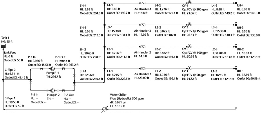
Figure 1. Closed-loop cooling system with four circuits (Graphics courtesy of the author)

Each of the four circuits shares a number of common elements, moving clockwise from the common return header (RH-1) through the water chiller and pipe, back to Pump P-1, and out to the common supply header (SH-1). At this point, each circuit has its own combination of process and control elements before rejoining at RH-1.

Next, we will look at how the fluid energy changes as it moves to the first circuit through Air Handler 1. At the suction side of the pump (P-1 In), the energy grade is a little more than 45 feet of head. Pump P-1 adds 227 feet of head to the fluid, bringing the fluid energy at the discharge to 272 feet. The fluid travels through pipe P-1 Out and the common leg of the supply header SH-1, where the energy grade drops to a little less than 231 feet because of friction losses and elevation change.

Following the fluid through the first loop, the head drops to less than 223 feet of fluid at the outlet of pipe L1-1. The head loss through Air Handler 1 is 23 feet to a little more than 199 feet of fluid.

At the outlet of pipe L1-2, going into the control element CV1, the energy grade is 196 feet. Control valve CV1 has a head loss of almost 65 feet, resulting in fluid energy of more than 131 feet at the inlet of pipe L1-3. The fluid flows through L1-3 and the common return header RH-1, resulting in an energy grade of less than 91 feet of fluid at the inlet to the water chiller. The energy level drops 16 feet through the chiller, then flows through three more pipe segments (C-Pipe 1, C-Pipe 2 and P-1 In) to return to the energy level noted previously at the suction side of the pump.

If we work through the rest of the circuits in the same manner, we arrive at the results shown in Table 1.

Energy used or added for each circuit
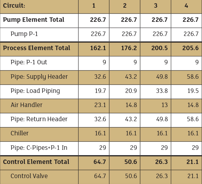
Table 1. Energy used or added for each circuit by piping system element (all values in feet of fluid)

Taking a look at the overall data, we can make a few observations. First, because the same pump element is driving the fluid through all four loops (Pump P-1), the energy added for each loop is the same: 226.7 feet of fluid. Second, while the head loss in the process elements and the head loss for the control elements are different for each loop, the total head loss for the control and process elements is always equal to the pump head (the energy added to the fluid by the pump). Lastly, the control elements—the control valves—are consuming 10 to 30 percent of the energy the pump adds to each loop.

For installations where lowering operational costs is a priority, further system analysis and optimization is possible to reduce energy that is not being used directly for the process elements.

In a multi-loop system typical of HVAC and other distributed service installations, each loop typically contains all three of the piping system elements: pump, process and control. The head loss from the process and control elements in each of these loops is equal to the pump head added by the pump elements.

To read more Pump System Improvement columns, click here.