
In Henderson, Nevada, P-19A is one of the most critical potable pump stations operated by the city. It supplies drinking water to the second largest city in Nevada. The station was put in service in 1999 with three vertical turbine pumps. Each pump was driven by a six-pole 700-horsepower (HP) vertical induction motor. Two additional vertical pumps, also driven by six-pole 700-HP vertical induction motors, were installed in 2006. Routine machinery vibration surveys taken at the station in November 2014 identified possible early stages of bearing failure, but no additional mechanical or electrical issues were detected. The vibration summary concluded that all pumps were operating within acceptable limits and no maintenance was necessary.
Overheating Motors
In January 2015 the motors for pumps 1 and 5 exhibited overheating as well as current and speed fluctuations. A variety of de-energized and energized diagnostic tests were conducted—including a rotor inductance test (RIT), vibration testing, a manual rotor test and a 10-second current trace. De-energized tests showed all measurements were balanced, which meant there were no indications of winding issues. Machinery vibration data again indicated early bearing degradation, but no additional electrical or mechanical issues.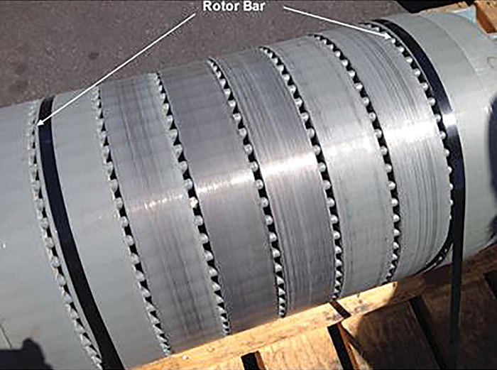 Image 1. Unit #5 damaged rotor (Images and graphics courtesy of City of Henderson)
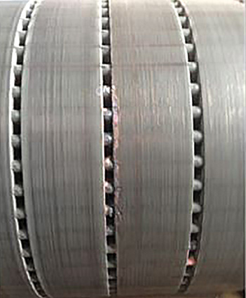 Image 2. Rotor showing damaged rotor bar areas
Electrical Signature Analysis
ESA is a diagnostic technology that uses the motor supply voltage and operating current to identify existing and developing faults throughout the motor system. ESA performs simultaneous data acquisition of all three phases of voltage and current to create a three-phase power-quality table. Additionally, it digitizes and stores the voltage and current waveforms for additional processing and analysis using fast Fourier transforms (FFT). During the motor tests, ESA data was taken at different times: first shortly after start-up, then again after the pump had been running for about 30 minutes. The most significant finding was the large change in rotor speed with a very small change in motor load. The rotor was running considerably below nameplate. After running 30 minutes, the rotor speed was 1,171 rpm. This was confirmed by a handheld tachometer used by the vibration analyst while taking the vibration data.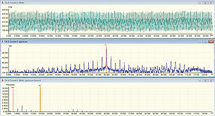 Figure 1. Software display of the low frequency data before repair.
Rotor Bars
Rotor bars are copper or aluminum bars that run the length of the rotor in alternating current (AC) squirrel cage induction motor rotors. These parallel bars are connected to rings—called end rings or shorting rings—on either end of the rotor providing a path for current flow through the rotor. Current flowing through the bars creates an electromagnet. Since these bars create parallel paths, the voltage across each path is the same and current flow through each path will vary depending on the resistance of each path. If the rotor bars develop cracks, separate from the end ring or have other imperfections, the resistance of the bars will increase and the current flow through the affected bar will decrease. Induction motors rely on the rules of mutual inductance to get power onto the rotor of a squirrel cage rotor. These rules (Faradays first law of electromagnetic inductance) require:- a magnetic field
- a path for current flow
- relative motion between magnetic field & conductor
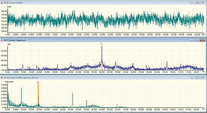 Figure 2. May 5, 2015 – ESA after repairs. Pole pass frequency side bands were gone and current draw was 754 amps with 2 amps modulation.
Symptoms of Rotor Bar Issues
When the rotor has unbalanced current flow through the rotor bars, it causes the rotor current to vary as the affected bars pass under the magnetic fields on the stator. Due to the difference of the rotational speeds between the rotor and the rotating magnetic field, each rotor bar will pass under each of the magnetic field poles each revolution of slip. For example, in a six-pole motor induction motor, there will be three north poles and three south poles. Therefore, when squirrel cage induction motors have rotor bar issues, the motor’s current modulates at a frequency equal to the number on poles on the motor times the frequency of the current flow through the rotor. This frequency is commonly referred to as Pole Pass Frequency (PPF), which is equal to the number of poles in the motor times slip speed.ESA FFT Results & Analysis
The results of the FFTs on pump motors 1 and 5 provided clear indication of rotor bar damage. The ESA automatic analysis software applies a proprietary algorithm that uses five criteria of the ESA analysis to identify rotor bar issues and to determine the severity of the problems. The software provides the charts, tables and graphs of the motor data, as well as detailed analysis report with actual recommendations.- Amplitude of PPF sidebands in current spectrum
- Motor load
- PPF amplitude in demodulated spectrum
- PPF harmonics in demodulated spectrum
- PPF sidebands around running speed spectral peaks
