
Q. What is NPSH3, and what are the methods for determining the NPSH3 of a rotodynamic submersible pump?
A. NPSH3 is the net positive suction head available to a pump under test at a constant rate of flow when the pump head is decreased by 3 percent as a result of cavitation caused by a decreasing available suction head. Sometimes NPSH3 is referred to as net positive suction head required (NPSHR); however, a pump's NPSHR must be higher than the NPSH3 for the pump to operate without head reduction, and it may need to be higher than the NPSH3 for long-term reliable operation. For more information on the required margins above NPSH3, refer to ANSI/HI 9.6.1 Rotodynamic Pumps Guideline for NPSH Margin.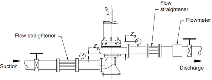 Figure 11.6.7.2a. Suction throttling NPSH test setup
This simple arrangement usually is satisfactory for NPSH greater than 3 meters (10 feet); however, the turbulence at the throttle valve tends to accelerate the release of dissolved air or gas from the liquid as the pressure on the liquid is reduced. A test made with this arrangement usually indicates higher NPSHR than what would be expected with deaerated liquid.
Figure 11.6.7.2b shows a second option. The pump is supplied by a sump in which the liquid level can be varied to establish the desired NPSHR. Be careful to prevent entrained air or vortexing as the liquid level is varied. The priming connection should be installed above the eye of the impeller, either in the discharge pipe or on the pump.
Figure 11.6.7.2a. Suction throttling NPSH test setup
This simple arrangement usually is satisfactory for NPSH greater than 3 meters (10 feet); however, the turbulence at the throttle valve tends to accelerate the release of dissolved air or gas from the liquid as the pressure on the liquid is reduced. A test made with this arrangement usually indicates higher NPSHR than what would be expected with deaerated liquid.
Figure 11.6.7.2b shows a second option. The pump is supplied by a sump in which the liquid level can be varied to establish the desired NPSHR. Be careful to prevent entrained air or vortexing as the liquid level is varied. The priming connection should be installed above the eye of the impeller, either in the discharge pipe or on the pump.
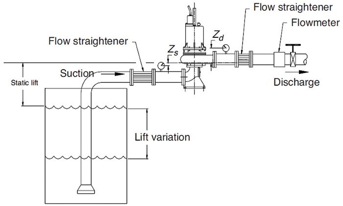 Figure 11.6.7.2b. Variable-lift NPSH test setup
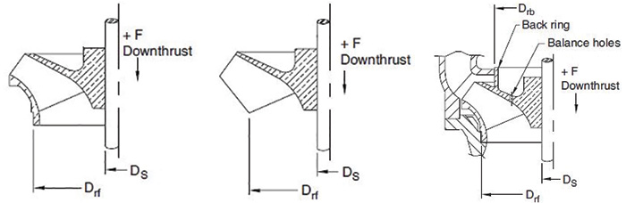 Figures 2.3.3.2.3a, b & c. The first (left) shows the enclosed impeller plain top shroud, the second (middle) displays the semi-open impeller and the third (right) illustrates the enclosed impeller with back ring and balance holes.