02/17/2016
This month's column focuses on whether to use shaft sleeves in overhung centrifugal pumps (Type OH-1 per American Petroleum Institute [API] 610 designation). The most common OH-1 pump type is the American National Standards Institute (ANSI) B73.1M. The practice of using cartridge-type mechanical seals on solid pump shafts (in lieu of sleeved shafts) is not new or radical. While the benefits of building a pump in this manner are real and measurable in most instances, a large percentage of pump owners will not change.
Background
I would estimate that shaft sleeves have been used on pump shafts for at least 100 years. My 1919 edition of Pumping Machinery by Arthur M. Greene mentions "sacrificial shaft liners." I do not know exactly when the first pump shaft sleeve was put into service, but I assume it was not long after someone adjusted the packing incorrectly on an expensive pump. Shaft sleeves serve multiple purposes. The most important is to protect the main pump shaft from wear caused by packing abrasion, followed closely by prevention of erosion and corrosion. In some pump designs, the sleeve serves additional purposes. For example, in some horizontal split-case pumps, the sleeve also serves (in conjunction with a threaded shaft nut) as an adjustable means to axially locate the impeller on its respective mechanical and hydraulic center in the casing. The sleeve is designed to be the inexpensive and replaceable part. It is easier and less expensive to change a sleeve than the whole shaft. Users who have packing in their pump consider the sleeve a must-have design feature. In 1905, the mechanical seal as we know it was invented, but it was not commonly used until after World War II. Fifty years ago, most centrifugal pumps in industrial and commercial services still had packed stuffing boxes. Pumps with mechanical seals were uncommon and expensive. Later in the 1970s, many users began to use simple mechanical seals because of safety concerns, stricter Environmental Protection Agency (EPA) regulations, and the cost of both lost product and flush fluids. These simple seals were eventually displaced by component type mechanical seals. Prudent pump users continued to use the existing shaft sleeve designs because the component seals were held in place by tightening a number of set screws. The torqued set screw points damaged the shaft sleeve surface. These "dog marks" (damaged metal surfaces) from the set screws were an accepted negative side effect because of the shaft sleeve's status as an inexpensive and replaceable part. In recent years, most pump users have switched to cartridge-type mechanical seals. Most present-day designs will not damage the shaft or shaft sleeve during installation, operation and subsequent removal from service. Even O-ring fretting of the shaft or shaft sleeve is eliminated in most new designs. When the American Voluntary Standards (AVS) pumps and the forerunners of the modern ANSI pump (B73.1M) were designed in the late '50s and early '60s, packed stuffing boxes were standard. If these pumps were to be redesigned today, they would use cartridge-type mechanical seals, and the design length of the shaft from the radial bearing to the impeller would be shorter. When a packed pump is operating, the packing acts like an additional line bearing because of the hydrodynamic properties of the close clearances between the shaft sleeve and the packing. This "consequential and beneficial phenomenon" mitigates shaft deflection caused by any unequal radial forces acting on the impeller. Without packing around the shaft (for example, when a seal is used), the shaft will deflect more, especially if the pump is not operating near the best efficiency point/best operating point (BEP/BOP). Pump operation at or near shutoff (far left side of the curve) and at runout conditions (far right side of the curve) away from the preferred operating region results in shaft deflection, which causes premature bearing and mechanical seal face wear, shortening the life of these critical components. The ability of a shaft to resist deflection is a direct function of the overhung length and the shaft diameter. This is commonly referred to as the shaft stiffness ratio, shaft deflection ratio, or the L over D ratio (L3/ D4). The lower the ratio number, the better the shaft will resist deflection. The formula for calculating the ratio factor is based on the simple cantilevered beam deflection formula. Many of the factors in the beam deflection formula cancel each other out when applied to an overhung pump shaft. As a result, the revised formula is simply the length (L) of the shaft as measured from the centerline of the radial bearing position to the centerline of the impeller (take L to the third power) divided by the diameter of the shaft in this area (D) to the fourth power, or L3/ D4 (see Figure 1).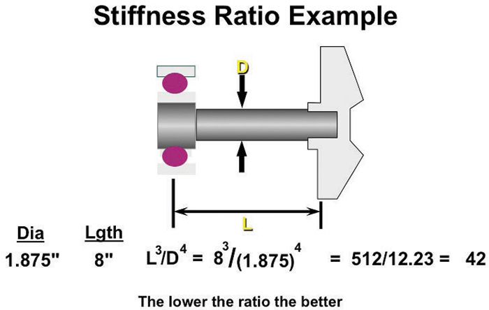 Figure 1. An example of stiffness ratio calculations (Graphics courtesy of the author)
Current Practices
Many pump owners continue to use old design shaft sleeves when using new design cartridge mechanical seals. There are some good reasons, such as corrosion/erosion mitigation, for continuing this practice. In most cases, however, there is no other reason than "that is the way we have always done it." I would say that, for a given system (curve) and the consequential pump operation on its curve, the pump life would be much longer if the shaft design was solid versus sleeved. The pump would be more reliable, and the mean time between failure and repair (MTBF/R) would be longer. In some modern OH-1 pump models, the incorporation of a shaft sleeve is by design and is an acceptable practice because the shaft deflection ratio is already very low as a result of a generous shaft diameter in the sleeve area. X-17 ANSI pumps (ANSI sizes A105, 110 and 120) are one example (see Figure 2, page 18).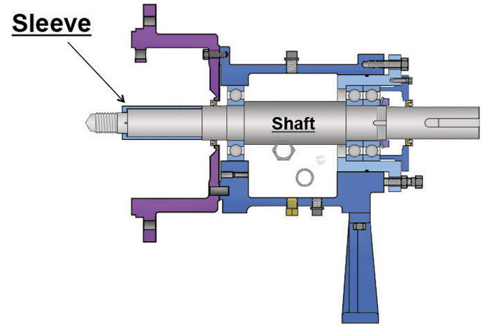 Figure 2. An example of a sleeved pump shaft design with ample diameter to maintain a low stiffness ratio
To read other articles in the 'Common Pumping Mistakes' column, go here.