
Last month’s column explored the effects that oversizing a pump has on the motor driving the pump, the adverse results of a pump no longer operating at its best efficiency point (BEP) for extended periods of time and situations in which a design margin could increase cost of ownership.
This column will explore pipelines in detail, consider how they affect the operation of piping systems, and review the method for calculating head loss in pipelines.
A pipeline is a circular conduit used to convey process fluid from one location in the system to another. A pipeline consists of a circular pipe full of fluid, the process fluid, and the valves and fittings used to direct the flow of fluid through the pipe in the operation. Each of these items affects the head loss in the pipeline. Most fluids used in industrial applications are Newtonian, meaning that their viscosity does not change with the rate of flow. Water, oils, solvents and petroleum products are examples of Newtonian fluids. For simplification this discussion will be limited to the flow of Newtonian fluids through circular pipelines.
Head Loss in a Pipeline
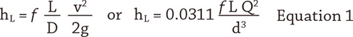
When fluid flows inside a pipeline, friction occurs between the moving fluid and the stationary pipe wall. This friction converts some of the fluid’s hydraulic energy to thermal energy. This thermal energy cannot be converted back to hydraulic energy, so the fluid experiences a drop in pressure. This conversion and loss of energy is known as head loss. The head loss in a pipeline with Newtonian fluids can be determined using the Darcy equation (Equation 1).
Where:
hL = Head loss (feet of fluid)
f = Darcy friction factor (unitless)
L = Pipe length (feet)
D = Inside pipe diameter (feet)
v = Fluid velocity (feet/sec)
g = Gravitational constant (32.2 feet/sec2)
d = Inside pipe diameter (inches)
Q = Volumetric flow rate (gallons/minute)
Evaluating the Darcy equation provides insight into factors affecting the head loss in a pipeline. If the length of the pipe is doubled, the head loss will double. If the inside pipe diameter is doubled, the head loss will be reduced by half. If the flow rate is doubled, the head loss increases by a factor of four. With the exception of the Darcy friction factor, each of these terms can be easily measured. In this case, little information about the properties of the process fluid or the surface roughness on the inside of the pipe material is available. Although these factors seem to most people to have an effect on head loss, the Darcy equation does not account for them.
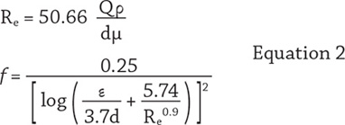
The Darcy friction factor takes the fluid properties of density and viscosity into account, along with the pipe roughness. The Crane TP-410 manual provides the
tables and formulas needed to perform the head loss calculations. It also includes a copy of the Serghide Explicit equation and the Swamee-Jain formulas allowing for direct calculation of the Darcy friction factor.
The Swamee-Jain equation is solved in two parts (see Equation 2). The first step requires calculating the Reynolds number of the fluid in the pipeline. During this step, fluid properties of density and viscosity are considered. The pipe absolute roughness value and Reynolds number are then used to calculate the Darcy friction factor.
Where:
d = Inside pipe diameter (inches)
Re = Reynolds number (unitless)
Q = Volumetric flow rate (gpm)
ρ = Fluid density (lb/ft3)
μ = Fluid viscosity (centipoise (cP))
f = Darcy friction factor (unitless)
ε = Pipe absolute roughness (inches)
The example below uses Equation 2 to calculate head loss in a 100-foot section of a 4-inch, schedule 40 steel pipe with a flow rate of 400 gallons per minute (gpm).
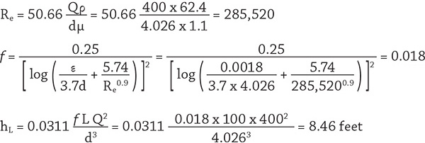
The calculation shows a head loss of 8.46 feet of fluid. Next, we will determine what happens when the flow rate is changed. Since this pipeline was calculated with a flow rate of 400 gpm, this example will calculate the head loss for 200 gpm and 800 gpm through the same 100-foot section of 4-inch, steel schedule 40 pipe.
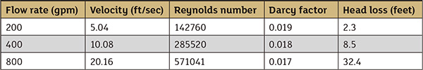 Table 1. Head loss in a 100-foot section of 4-inch schedule 40 steel pipe with different flow rates. Notice the Darcy friction factor varies with the flow rate. (Graphics courtesy of the author)
A rule of thumb for pipeline head loss is doubling the flow rate increases the head loss by a factor of four. This is because the flow rate is raised to the second power. As Table 1 shows, doubling the flow rate doubles the fluid velocity and Reynolds number.
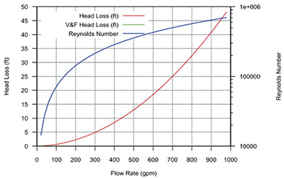 Figure 1. The Reynolds number and the head loss for the pipeline data listed in Table 1. The greater the flow rate, the greater the rate of head loss increases.
Using the doubling flow rate rule, the 200 gpm flow rate with its head loss of 2.3 feet would result in a head loss of 9.2 feet instead of the calculated value of 8.5 feet. Using the doubled rate, the 400 gpm flow rate with its corresponding 8.5 feet of head loss results in a head loss of 34.0 feet of fluid rather than the calculated value of 32.4 feet. The rule only provides an estimate.
Pipe Material
Often the construction material limits the available pipe sizes and schedules. For example, polyvinyl chloride (PVC) pipe is available in many of the same sizes as steel pipe, but it is only available in schedule 40 and 80 pipe dimensions. However, the inner pipe diameter (ID) can be different, providing varying results in head loss. Table 2 compares the absolute roughness values for different material with a 4-inch, schedule 40 steel pipe with 60 F water with a 400 gpm flow rate.
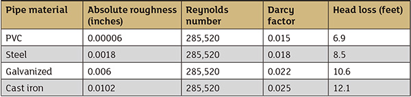 Table 2. Head loss in a 100-foot section of pipe transporting 60 F water through a pipe with an ID of 4.026 inches and various absolute roughness values
The Darcy friction factor varies widely with pipe roughness. As the pipe wall roughness increases, the head loss increases.
Pipe Size
Pipe is available in different sizes and schedules or wall thicknesses. Users often mistakenly use the pipe’s nominal size instead of the actual ID when performing the head loss calculations. Table 3 shows the available schedules for 4-inch steel pipes along with the corresponding ID, fluid velocity and head loss when 400 gpm of 60 F water is flowing.
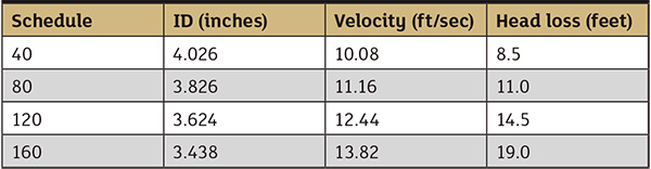 Table 3. Head loss and fluid velocity in a 100-foot section of 4-inch nominal size steel pipe using the available schedules when transporting 60 F water at 400 gpm
The choice of the pipe size has a major effect on the head loss in the pipeline. Table 4 shows the nominal sizes available for steel schedule 40 pipe. In each pipeline the ID, fluid velocity and head loss is displayed for a 100-foot section of steel schedule 40 pipes when transporting water at 400 gpm.
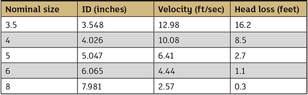 Table 4. The head loss and fluid velocity in a 100-foot section of schedule 40 steel pipe using the available sizes when transporting 60 F water at 400 gpm
In Table 4, the head loss drops rapidly as the ID increases. For example, transporting water through a 3.5-inch pipe results in 16.2 feet of head loss, while a 6-inch pipe has a head loss of only 1.1 feet. This reduction in pipeline head loss allows for the selection of a smaller pump that requires less power. A larger pipe, however, costs more to purchase and build.
The Crane Technical Paper 410 recommends a fluid velocity in the range of 5 to 10 feet per second (ft/sec) in a pump discharge pipeline, and a fluid velocity of 2.5 to 5 ft/sec on the pump suction pipeline when the fluid is water. This is an engineering cost decision—either pay more for the pipe and less for the pump and pumping cost or vice versa. Proper understanding can lead to finding the optimum pipe size based upon fluid velocity. Equation 3 can be used to determine the optimum pipe ID for a given flow rate.
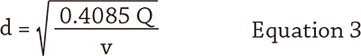
Where
d = optimum inside pipe diameter (inches)
Q = flow rate (gpm)
v = fluid velocity (ft/sec)
For example, consider what diameter should be chosen to pump fluid at 600 gpm through steel schedule 40 pipes with a sizing velocity of 8 ft/sec. The ideal pipe size for this condition is 5.535 inches, but this example is limited to given pipe sizes. Table 4 shows that a 5-inch pipe has an inside diameter of 5.047 inches and a 6-inch pipe has an inside diameter of 6.065 inches.
Process Fluid
The fluid properties also affect the head loss in a pipeline. This example demonstrates what happens when a change of both process fluid and temperature occurs. Table 5 displays the head loss when pumping 400 gpm of different process fluids at different temperatures through a 100-foot-long, 4-inch schedule 40 steel pipe. This example compares head loss for water, a 40-percent solution of sodium hydroxide (NaOH) and an oil-based heat transfer fluid (HX). All calculations are performed at 60 F and 160 F.
Greater fluid viscosity results in greater head loss. Some fluids may require external heat tracing to keep them at a flowing temperature. Any change in the process fluid or fluid temperature should be investigated to see how it affects the pipeline head loss.
Next month, this column will evaluate the effects fittings, check and isolation valves have on the head loss of the pipeline. Additionally, it will demonstrate how to calculate the operating cost of pipelines to help identify ways to optimize piping systems.
