Submergence is a commonly overlooked pump suction side issue that can create mechanical and hydraulic performance problems. Insufficient submergence can lead to increased vibration, a broken shaft, shortened mechanical seal life, premature bearing failure, lower flow rates and diminished discharge heads (pressure) for the pump. In the worst cases, these issues will cause surging and will actually stall (air block) the pump. Submergence (simple submergence) is defined as the distance (D) measured vertically from the surface of the liquid to the centerline of the inlet suction pipe. A more important term is required submergence, also known as minimum or critical submergence (SC). Required submergence is the vertical distance—from the fluid surface to the pump inlet—required to prevent fluid vortexing and fluid rotation (swirling and or pre-swirl). Vortexing will introduce unwanted air and non-condensable gases, which can cause pump damage and reduce pump performance. A centrifugal pump is not a compressor, and performance is greatly affected when pumping dual and/or multi-phase fluids (gas and air entrainment in the fluid). A common misconception is that inadequate submergence issues are found only on vertical and/or very large pumps. This issue, however, can and will occur on small and/or horizontal pumps. When a centrifugal pump operates at a given flow rate (Q), there is a corresponding fluid velocity in the suction line (V). You can calculate this velocity easily by using Equation 1 or by simply looking it up in references such as Cameron Hydraulic Data (Chapter 3) or Crane Technical Paper No. 410, Flow of Fluids. The velocity of the fluid is an important value to know because it will determine the correct submergence required to prevent the formation of vortices. Figure 1 shows two separate cases; both are for a flow rate of 300 gallons per minute (gpm), but the suction pipe diameter is 4 inches in one case and 6 inches in the other.
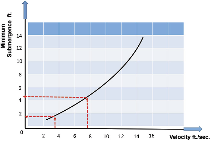 Figure 1. General guide for minimum submergence based on fluid velocity (Courtesy of the author using data from Hydraulic Institute)
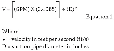
12 Tips to Remember
- Critical submergence (SC) must be greater than simple submergence to prevent vortex formation, but it is still not a guarantee of vortex preclusion.
- Pumps that are larger, vertical and/or with impellers of higher specific speeds are generally more sensitive to submergence issues, but all centrifugal pumps are susceptible.
- Opening impeller clearances by a factor of three to four times the normal measurement can allow air and gas to pass through the pump with fewer negative effects, but the efficiency, related brake horsepower and cost of operation will be greatly affected. Do not open clearances without consulting the OEM first.
- There are various stages, strengths and states of vortex generation including incipient, invisible, surface and subsurface. Just because the vortex is not visible to the naked eye does not mean it is not present. The vortex size is a function of the residual angular momentum of the fluid at that point.
- In respect to suction tank or sump design, if the intake pipe is horizontal, a vertical wall (90 degrees) is better than one with a slope (less than 90 degrees).
- When referencing charts for calculating minimum submergence, keep in mind that the assumption is that no obstructions or asymmetrical geometries are in the tank/sump.
- Do not confuse submergence with net positive suction head available (NPSHA). I always recommend that both values be calculated for the worse expected condition. You can have adequate NPSHA and still not have proper submergence and vice versa.
- Critical submergence is a function of factors besides the vertical distance and the acceleration of gravity. Other factors are surface tension, viscosity, density and the diameter of the suction pipe opening, especially if there is a transition to a smaller-diameter pipe shortly after the initial opening. Pay specific attention to the ratio of the diameter changes. With surface tension, it is a very small factor. In the case of viscosity, it will depend on the Reynolds number, which is defined as the ratio of momentum forces to viscous forces and quantifies the relative importance of these two types of forces for given flow conditions. Think of it as the amount of turbulence.
- In some cases, you can have too much submergence for a given system design, from the aspect of siphon effects. This is rare.
- Suction (pipe) velocities to the pump should be kept between 5 and 8 feet per second. I recommend not more than 6 feet per second unless there is a requirement for suspended solids (critical carry velocity) and other slurry rheology concerns.
- The suction tank/sump should be sized and designed so that the volume has five to eight minutes of hold time. For example, if the pump is designed for 200 gpm then the tank should be 1,000 to 1,600 gpm in effective volume. Proper addition of barriers, baffles and weirs can reduce the required size.
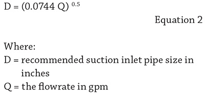
- As a general guideline only, the recommended suction inlet pipe size (D) can be calculated using Equation 2. I always recommend rounding D up to the next pipe size, not down.