
Facilities predominantly using these drives may face concern from power utility companies.
12/28/2015
Variable frequency drives (VFDs) have vastly evolved during the last 25 years. Hundreds of articles have been written about their advantages when used with a pump motor compared with an across-the-line motor and flow control valve. One primary benefit occurs when slowing the motor speed leads to reduced kilowatts, resulting in reduced electrical usage. When the electrical loading of a facility is predominantly made up of VFDs, some would view this as a success story. The power company, however, might disagree because VFDs can add unwanted harmonics to the system.
Advantages of VFDs
VFD sizes are smaller, their intelligence is greater and the cost has remained flat despite other industrial products following inflation prices. VFDs dominate variable torque applications like those found in pumps and fans. VFDs are noted for their precise motor control output, but rarely is the VFD's input discussed. The VFD's input configuration sets the stage for how clean the power consumption will be. Before the advent of VFDs, power companies had to deal with across-the-line motors. Lightly loaded motors had poor power factor, and starting these motors meant short-term heavy demands on the system. Both would warrant a penalty on the user. VFDs remove this concern, but with the popularity of VFDs increasing in facilities, the harmonics content created by VFDs increases as well. Utilities are taking note of this new phenomenon. Exploring the VFD inputs can help end users find clarity about harmonics.Basic VFD Topology
To change the speed of an alternating current (AC) motor, the voltage and frequency must be varied proportionally. VFDs use traditional AC to direct current (DC) conversion and then invert DC to AC to change both the voltage and frequency to the motor. This method can best be explained by splitting the VFD into three parts (see Figure 1).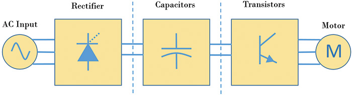 Figure 1. Power components used in VFDs to convert fixed line voltage/frequency to variable voltage/frequency (Graphics courtesy of the author)
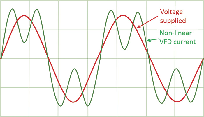 Figure 2. Line voltage in its purest form, shown with VFD non-linear current.
Harmonic Mitigation Options
There are several methods to reduce or eliminate the harmonics content that a VFD creates. One choice is to add an inductor, more commercially known as a reactor, to the input of the VFD. These are relatively inexpensive and will reduce the harmonic content from above 60 percent to the 40 percent range. This is significant cost and size reduction for a small device (see Figure 3).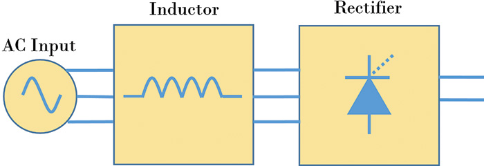 Figure 3. A reactor is placed in front of the VFD. Reactors slow the current fluctuations and thus reduce harmonics.
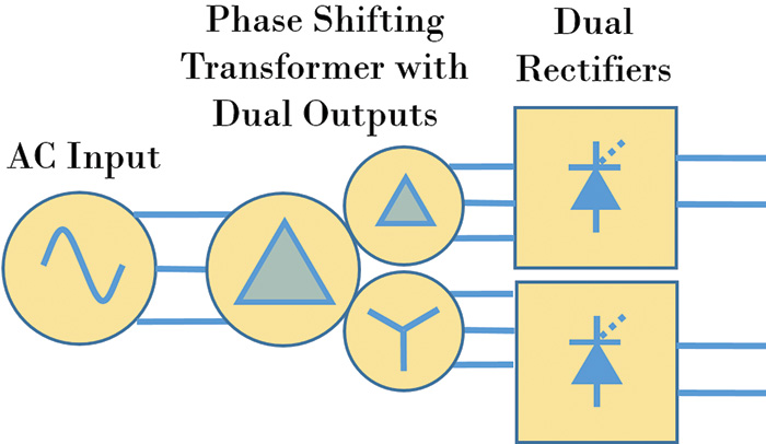 Figure 4. A 12-pulse VFD is an alternate type of VFD that has less harmonics than a six-pulse VFD, but requires a special Delta-Delta/Wye transformer.
Harmonic Filters
An alternative choice for harmonics correction is to use harmonic filters. These come in many different configurations, but the two primary options discussed here are passive and active. Passive filters consist of passive electrical components, capacitors and inductors, configured to trap or notch offensive frequencies. These perform best at rated loads and should be sized accordingly. Expectations with this device are less than 8 percent THDi. Be aware that the amount of harmonic correction begins to deteriorate with passive devices at lighter loads (see Figure 5).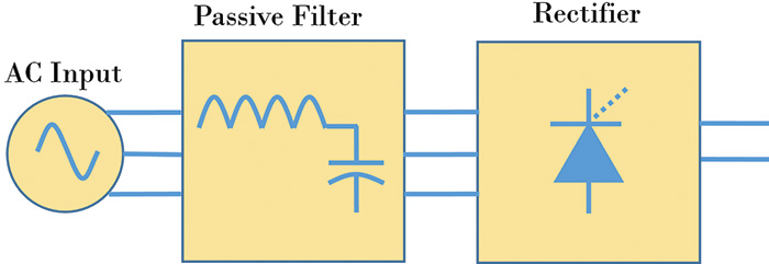 Figure 5. A passive filter is a series device that goes in line with the VFD.
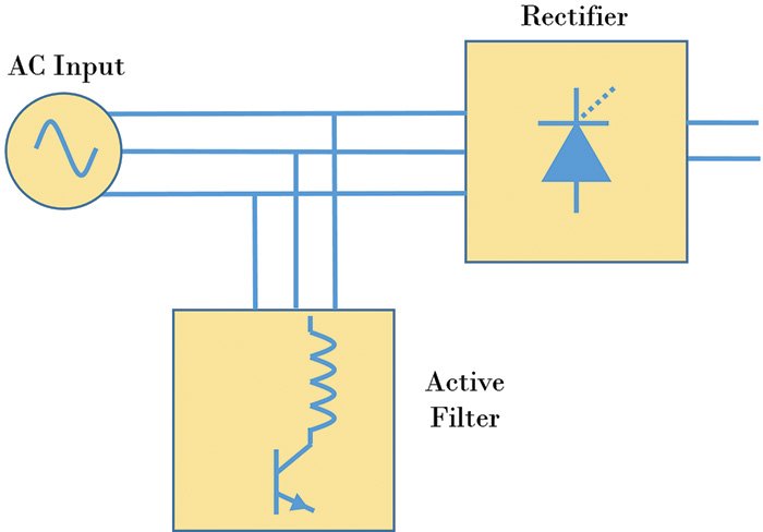 Figure 6. An active filter is a parallel device that goes in parallel with one or more VFDs.
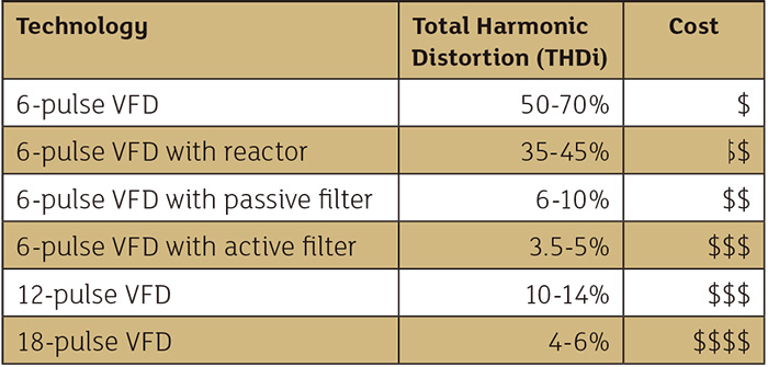 Table 1. Many technologies exist to keep harmonics mitigated.