A software simulation tool and detailed engineering analysis procedure are needed for 
problem solving.

Successful field engineering requires many of the same tools and techniques as traditional development engineering. For the purposes of this article, “field engineering” can be thought of as the application of engineering to solve a problem with a machine or system after it has been designed and installed.

A logical, detailed analysis approach must be used in conjunction with the appropriate engineering analysis hardware and software. Often, field engineering efforts degenerate into a trial-and-error approach, which does not achieve an optimal, cost-effective solution. Pressure from management to get a system online and running or to ensure adherence to a project schedule often force temporary fixes or poorly developed solutions, which ultimately detracts from the long-term reliability and increases life-cycle costs of the equipment.

If a field engineering effort is approached with the same methodology as a new project or design problem, the outcome will be a superior solution. This is true regardless of whether the problem lies within hydraulic system or is a mechanical equipment issue.

To illustrate this concept, this article will start with a basic “engineering analysis” procedure:

Original base with first 'field fix'
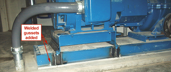
Figure 1. Original base with first “field fix”
  • Clear problem statement
  • Information gathering
  • Defining assumptions and limitations
  • Selecting appropriate governing equations
  • Calculations (or simulation) and solution generation
  • Alternative selection and implementation

The list shows a clear progression from the problem to the solution and the steps required to accomplish this.

Consider the typical trial-and-error approach:

  • Vague problem statement
  • Trial solution
  • Feedback (Did it work?)
  • Another trial solution
Drawing of new motor saddle
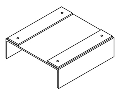
Figure 2. Drawing of new motor saddle

This cycle generally continues until either a “good enough” solution is implemented or the project over-runs its cost thresholds and higher level corrective actions are initiated. The time, effort and cost required to solve a field problem is usually much less if the engineered approach is used as opposed to the trial-and-error approach.

This occurs because most trial solutions are not based on a thorough engineering analysis, but instead are implemented based on past experiences with similar equipment or because fixes are designed without complete information. Statements such as, “We reduced the vibration on another pump like this one a few years ago by changing the coupling to a different style, so we decided to do the same to this one,” are common.

While well-intended, the chances of successfully mitigating the problem were extremely low because a rigorous engineering approach was not used to solve the problem. The first step, which was a clear definition of the problem to be solved, was missed.

New motor saddle installed
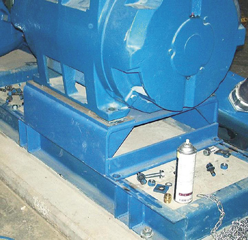
Figure 3. New motor saddle installed

A Case Study

The following case history is offered to illustrate the concept. A new manufacturing plant was being constructed near Kansas City in early 2012 and the plant utilities building was close to completion. However, a problem was noted with the newly-installed chilled water circulator pumps. The pumps were between bearings, double suction centrifugal, 1,800 RPM, size 8x10-17 operating on VFDs. The reported problem was elevated turning speed vibration at higher operating speeds. Amplitudes of greater than 0.40 IPS-RMS were reported. This was unacceptable and the contractor was facing penalties on the project unless the issue was corrected in a short time frame.

The first field engineering effort proved unsuccessful in reducing the vibration and took approximately two weeks to work through at a cost of several thousand dollars.

The problem was investigated, but not enough to facilitate the engineering solution. In this case, the problem was identified as a resonant frequency using standard spectral vibration analysis, but no further investigation was performed to clearly define exactly which component(s) were involved, the mode shapes involved or the operating deflection shape of the equipment. The result was a vague definition of the problem.

The next steps were contacting the original equipment manufacturer (OEM) for support. This was a positive step, but without complete information and a clear definition of the problem, the suggested field fix from the OEM was ineffective. It involved welding gussets to several areas of the base (see Figure 1).

Experimentally measured first mode at 25 hertz
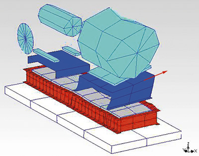
Figure 4. Experimentally measured first mode at 25 hertz

Later, when questioned about the field fix, the OEM stated that it had been their experience that this specific baseplate sometimes requires increased stiffening measures to minimize vibration levels when “larger” NEMA frame motors are used.

The additional bracing did not correct the vibration levels. Data that was provided after the first trial fix indicated that a resonance condition was still present within the operating speed range of the pump. Further corrective measures were examined, and it was decided to fabricate new motor supports from a thicker plate to further increase the rigidity of the motor base. Again, this was based on past experience in which thicker supports did not suffer this same problem.

A new “motor saddle” was fabricated from a ½-inch steel plate with ½-inch machined mounting pads and installed on one of the units. The vibration levels were reported to be “better” at the lower RPM ranges, but near maximum speed (1,800 RPM) the vibration levels were still unacceptable. It was suspected that the new saddle altered the natural frequency but had not shifted it high enough to be outside of the amplification range. Figures 2 and 3 are images of the new saddle.

The continued issues with vibration were causing unacceptable schedule delays for the end user’s construction project, so the author was asked to come to the site immediately to investigate and assist.

Adding 3/8-inch plate to the sides of the original motor support
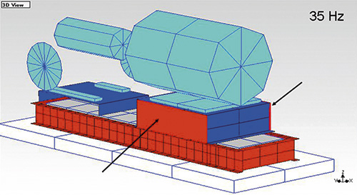
Figure 5. Adding 3/8-inch plate to the sides of the original motor support

After reviewing all available data on the pump system and the original field engineering efforts, it was determined that there still was not a clear understanding of the exact problem. Therefore, the author recommended specific analysis technologies and techniques be used to diagnose the problem.

In this case, in which a structural resonance is suspected but no deflection or modal data exist, it was necessary to conduct operating deflection shape (ODS) and experimental modal analysis (EMA) testing on the problem pumps. These specific techniques generated the necessary engineering diagnostic information to clearly define the problem that standard vibration spectral analysis cannot provide.

The results of the field testing were able to confirm the following:

  • The operating deflection shape at 1,498 RPM approximated the first mode shape indicating possible resonance.
  • The first mode was a lateral rocking of motor base at 25 hertz
  • The second mode was a longitudinal twisting of the motor saddle at 70 hertz
Adding 'wing' style supports, 3/8-inch plate steel material
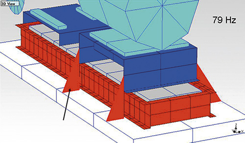
Figure 6. Adding “wing” style supports, 3/8-inch plate steel material

The same testing was also performed on the pump that been previously modified. By comparing the results from the two units, it was determined that the modifications implemented were able to increase the first natural frequency by nearly 15 percent. However, resonant amplification was still occurring above 1,680 RPM (28 hertz).

Applying the aforementioned engineering analysis methodology to the current problem, it became clear that steps one and two were complete. The problem was well understood; “A lateral rocking mode natural frequency of the motor base coinciding with operating speed at and above 1,498 RPM.” The ODS/EMA testing of the previously modified unit was part of the additional information gathering step as it informed what effect the structural modifications had on the original system.

  • The next step in the process was to define the assumptions and limitations. For this case, the list of assumptions and limitations looked similar to those listed below.
  • Shifting the first mode to a value greater than 15 percent higher than the maximum operating speed will eliminate the resonant condition.
  • The solution must be able to be fabricated and installed in less than one day per pump.
  • The solution must cost less than $1,500 per pump.
  • No piping or piping support modifications are allowed.
Both wings and side plates
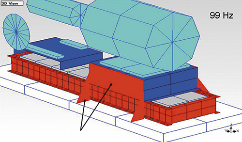
Figure 7. Both wings and side plates

There were more facets, but the idea is that any analysis and resultant solution has to take the boundary factors into account.

Specific Software Simulation Tool

Steps four and five involved the use of a specific software simulation tool. The governing equations for the engineering analysis are part of the software package and involve the equations of motion and the experimentally derived modal parameters (stiffness, mass, damping, etc).

The use of a software simulation tool allows the engineering analyst to simulate the impact of myriad structural modifications on the dynamics of the system. The goal is to determine what type of modifications would increase the first natural frequency of the motor/base assembly to 35 hertz or greater with a minimum of additional cost and effort.

The accuracy of the predicted effect from the structural dynamics modifications (SDM) simulations was checked by comparing the predicted effect of the previous modifications with the test data obtained on the modified pump. Agreement was determined between them, resulting in a high degree of confidence that the SDM predictions were accurate. The results of several example SDM simulations are shown in Figure 5. (The predicted natural frequency of the mode of interest is shown in the upper right hand corner.)

Wing-style support
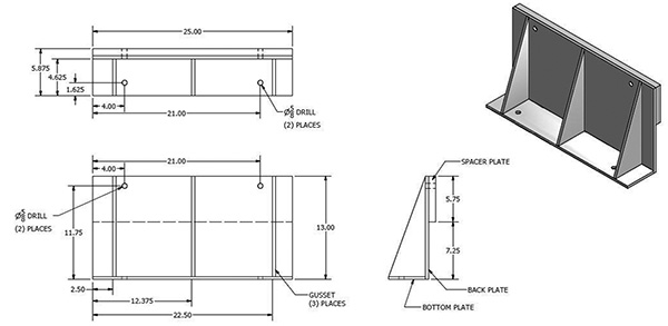
Figure 8. Wing-style support

Recommendations

Based on this analysis, the recommendation was made to design and fabricate a wing-style support that could be anchored directly to the foundation and then attached to the sides of the upgraded motor saddle. This alternative was selected based on a combination of factors—including the evidence that wing-style supports would have the greatest impact on the mode of concern, relative ease of installation, short time required for fabrication, and the desire to provide a robust and cosmetically acceptable solution.

A drawing of the base modification is shown in Figure 8. The support was designed to be anchored directly to the concrete foundation and then bolted to sides of the upgraded motor saddle. After installation, the vibration levels were tested again and determined to be acceptable (less than 0.10 IPS-RMS) throughout the entire RPM range with no indication of resonant amplification.

If the two field engineering efforts are compared, the advantages of the structured analysis approach become clear. The first effort consumed two weeks of time, occupied several different skilled resources, wasted several thousand dollars and ultimately did not correct the problem.

The structured engineering approach required less than a week to perform from start to finish and resulted in a robust, long-term solution which helped the contractor avoid penalties and maximized the equipment reliability at a minimum additional cost.

While this example was relatively simple, the same principle applies to more complex system issues. Usually, the more complex or difficult the problem becomes, the more significant the cost and time difference between the engineered approach and that of trial and error becomes.

Issue