
When a severe pump failure involving one of three installed circulating water makeup pumps happened, facility personnel grew concerned about the root cause. The subject pump failed just 40 days after its commissioning.
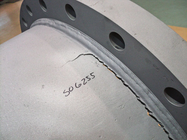
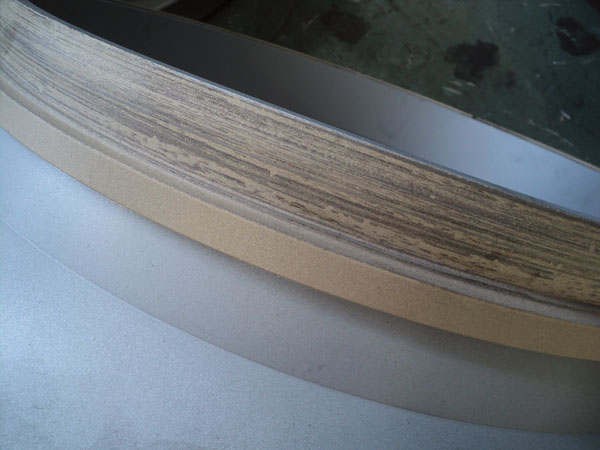
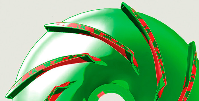
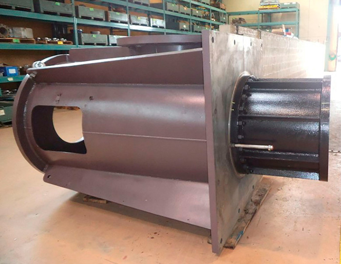
The equipment in question consisted of three-stage vertical turbine pumps running either in standalone or in parallel operation as required. The failure manifested itself through high vibration and caused severe scoring of the pump shaft and wear ring landings, leading to fatigue failure of the weld on the discharge head flange (see Images 1 and 2).
The commissioned pump was refurbished and rebuilt by another company's service center with spare impellers supplied by an original equipment manufacturer. No changes to the geometry had reportedly been made, although the impeller material had been upgraded from bronze to stainless steel. The plant initiated its internal root-cause analysis process, and the failed pump required emergency repair. The station sought a company to conduct the repair, and the firm reviewed the customer-supplied documents and background providing the possible causes of the failure.
Root-Cause Analysis of Pump Failure
The line-shaft bearings and remanufactured bowl assembly were analyzed for mechanical and assembly root causes. The weld repairs were analyzed, and samples were sent to metallurgical laboratories for review by the end user. There were no apparent mechanical problems identified to point to the root cause of the failure.
After extensive mechanical analysis of the failure, the company conducting the repair performed a comprehensive root-cause analysis of the failure. This involved analyzing the possible geometry differences of the replaced impellers and their influences on the pump hydraulic performance, which possibly caused the failure.
Pump performance is determined and influenced largely by the geometry of the impeller and casing. If any changes to the geometry of these components occur, unintended consequences to the pump's performance can result.
Investigating Impeller Geometry Discrepancies
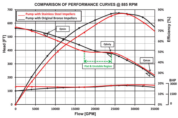
A thorough investigation of the machine's performance was conducted, and a detailed comparison between the stainless steel and bronze impellers showed considerable differences in the shape of the head and flow (H-Q) curve (see Figure 1).
From the analysis of the pump curves, engineers saw that the shape of the pump curve differed significantly from the original, suggesting a discrepancy in geometry. The newly supplied stainless steel impellers represented a relatively higher specific speed. Also, the head curve of the stainless steel impellers showed a flat area at the duty point. This allowed the pump to "hunt" across this area and created severe vibration that contributed to the pump's failure. As a result, the head curve of the stainless steel impellers was less stable than the original bronze design at the vicinity of the duty flow.
The pump with the stainless steel impeller also consumed more brake horsepower at the required maximum flow (Qmax). With this observation, engineers determined the unstable operation at the duty flow could have been the cause of the pump failure. This shows the importance of analyzing the impeller geometry and providing pump tests to ensure proper pump operations. The next step involved studying the difference in geometries of the bronze and stainless steel impellers.
Key Findings From Impeller Reverse Engineering
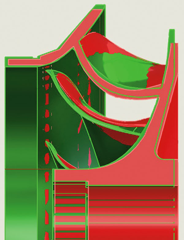
Using a comprehensive approach to impeller reverse engineering, experts established the differences between the stainless steel and the original bronze impellers. Significant differences in the vane shape and at the vane exit and inlet (at the impeller eye) raised concerns about the impeller geometry (see Figures 2 and 3).
The discharge vanes at the impeller outlet were considerably different, causing the discrepancy in head and curve shape. The inlet angles and geometry of the impeller inlets also showed significant deviations from the original design—meaning consequences for the machine's net positive suction head required (NPSHR).
Based on the geometry differences at the impeller inlet, it was noted that the required minimum submergence level for the pump with the stainless steel impellers might be relatively higher than the required minimum for the bronze impellers.
With this input, the plant reviewed the submergence data and confirmed the actual submergence level was at the minimum at the time of the pump failure. The minimum level for bronze impellers might not be sufficient for the stainless steel impellers, which could have compounded the problems of unstable operation and high vibrations.
Pump Repair Strategies & Long-Term Solutions
Instead of repairing the cracks on the discharge head flange by welding, engineers suggested a spool piece design, manufactured and mounted onto the discharge head (see Image 3). The stiffening ribs added to the spool provided extra strength.
The end user decided against the stainless steel impellers and reverted to the original design with bronze impellers. In order to conclusively identify the root cause of the pump failures, a comprehensive pump performance test was required.
To gain more insight into the unstable operation at any given flow, the engineers decided to take multiple flow data points from shutoff to Qmax (and also closer intervals in the order of 1,000 gallons per minute near the potential unstable range of flow), the standard vibration on the discharge head, and additional vibration on the bowl in submerged condition.
The new test curves were analyzed in conjunction with the plant-provided system curves for standalone operation and parallel operation. The team concluded that the presently tested bowl assembly was better-suited to go into standalone or parallel operation with the two existing sister pumps already operating at the station.
After extensive analysis and performance testing, engineers identified the failure mechanism. The geometry of the impeller had a significant impact on the shape of the performance curve. Poor geometry control through the material change process caused large deviations from the original geometry that led to a serious failure.
Best Practices for Design Changes
The manufacturing process must always be considered along with the design process when making changes to all aspects of the design, and robust checks should be in place to ensure site performance is not compromised. Performance testing of any upgrade is always valuable even when the upgrade is not hydraulic. Performance testing ensures that any pump can achieve its required H-Q curve shape, achieve acceptable vibration levels and perform correctly when installed.
For more articles on root cause analysis, click here.
