HI Pump FAQs

Q. What is water hammer, and what is its impact on a pumping system?
A.
Water hammer, or hydraulic shock, is a condition that exists when a column of fluid changes velocity quickly in a piping system. Water hammer has several causes, such as a pump start or stop or a rapid change of valve position. The velocity change results in a pressure wave that is above and below the normal pressure in the piping system. These pressure waves are called surge pressures or water hammer (when water is the fluid), and their magnitude can be sufficient to burst or collapse piping, valves, machinery casings and other devices.

The pressure wave’s magnitude can be calculated with reasonable precision if the user knows the configuration of the piping, the size of the pipes, the materials of the piping, the properties of the fluid, and how quickly the pump and/or fluid accelerates or decelerates. When the column of fluid in the piping is either started or stopped, the energy of the system is transformed from velocity energy to head or pressure energy. Because the fluid and piping material are not completely incompressible, they absorb a fraction of the energy.

Cast iron, for example, is a rather brittle material and is more susceptible to failure from sudden impact of a pressure wave that is well above its normal internal pressure and traveling at the speed of sound. Other materials that are more ductile may absorb the shock waves without cracking but still risk permanent deformation and failure. The pump is not the only component that is affected by this phenomenon; valves, sprinkler heads and pipe fittings are also at risk of catastrophic damage. Water hammer can adversely affect pipe hangers and pump foundations. Polyvinyl chloride (PVC) pipe and fittings are especially susceptible to damage from water hammer.

Surge analysis is necessary because surge will occur in every pumping system. Water has mass. One cubic meter of water at 15 C (59 F) weighs 1,000 kilograms (kg) (1 cubic foot [ft3] of water weighs 62.4 pounds, or 1 gallon weighs 8.3 pounds at sea level). Moving water has momentum, which is directly related to both the mass and the velocity of the liquid. The faster the liquid flows, the greater its momentum. The greater the momentum, the more damage water hammer can cause if the liquid is suddenly stopped. Surge pressure will be maximized when the fluid is stopped in less time than it takes for a pressure wave to travel from the equipment that stopped the flow to the other end of the piping system and back.

Water hammer can be understood through proper surge analysis and controlled through proper valve closure rates (with slow-closing valves), controlled starting and stopping of pumps, the addition of diaphragm tanks to absorb the pressure surge, and relief valves to release the pressure.

For more information on water hammer, refer to ANSI/HI 9.6.6 Pump Piping for Rotodynamic Pumps.

Q. How does the elevation from the suction gauge affect the NPSHA calculation?
A.
The NPSHA is the total suction head available over the vapor pressure of the pumped liquid corrected to the centerline of the impeller (or impeller inlet vane tip datum if vertically mounted) as shown in Figure 9.6.1.1a and measured at the inlet to the pump. An NPSH margin may be required for several reasons related to pump performance and service life.

Figure 9.6.1.1a. Datum elevation for various pump designs at eye of first-stage impeller
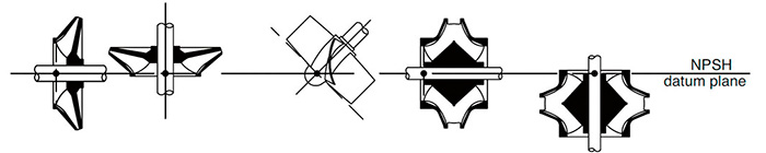
Figure 9.6.1.1a. Datum elevation for various pump designs at eye of first-stage impeller (Courtesy of Hydraulic Institute)

The margin can underline the uncertainties of what the NPSHA will be over the range of operation, and it can provide for adequate pump reliability and performance.

When calculating NPSHA based on suction pressure gauge measurements, note that the elevation difference between the gauge and the datum must be added to the NPSHA.

If the gauge elevation is above the datum, it will increase the NPSHA calculation. The opposite is true if the gauge elevation is below the datum. As noted previously, NPSH margin is required and is calculated as shown in Equation 1.

Equation 1
NPSHA = hatm + hs - hvp
NPSH margin = NPSHA - NPSH3

Where:
hatm = atmospheric pressure head, in m (ft)
hs = total suction head = hgs + hgs + zs, in m (ft)
hgs = suction gauge head, in m (ft)
hvs = suction velocity head, in m (ft)
zs = elevation from the suction gauge centerline to datum (see Figure 9.6.1.1a), in m (ft)
hvp = liquid vapor pressure head (taken at the highest sustained operating temperature), in m (ft)

NPSH3 is the point where a 3 percent head loss is observed at a constant flow rate asNPSHA is reduced. This is an accepted industry practice defining a condition of head breakdown resulting from cavitation and is used in the NPSH margin calculation.

For more information on NPSH, refer to ANSI/HI 9.6.1 Rotodynamic Pumps – Guideline for NPSH Margin.

Q. What are important environmental and operational considerations for wastewater pumps?
A.
Some important considerations are altitude, temperature of the liquid and speed of operations.

Altitude: The site elevation for the pump installation can affect pump operation. In general, the higher the installation’s elevation, the less suction lift there is available for the pump. For pumping systems with atmospheric suction pressure, the net positive suction head available (NPSHA) calculation should be corrected for the atmospheric pressure at the jobsite. Altitude will also affect the selection of the pump driver because the higher the altitude, the less cooling there is for the driver.

Temperature: The temperature of the pumped liquid affects the pump’s ability to operate. Specifically, as temperature increases, the vapor pressure of the liquid increases, which results in less NPSHA. When NPSHA is not sufficient, the pump will cavitate, which can cause reduced performance, physical damage to the pump components and increased vibration. The selection of the pump must include appropriate correction factors for temperature.

Speed: Solids-handling rotodynamic pumps are normally operated at speeds of 1,800 revolutions per minute (rpm) and below to reduce wear and susceptibility to clogging. The net positive suction head required (NPSHR) of the pump is approximately proportional to the square of speed change. Pump units can be operated with constant speed or variable speed drivers. Adjusting the speed of the pump driver will change the pump’s operational characteristics. Using a variable speed drive system can provide pump adjustment on a frequent basis. Variable speed operations can maximize reliability and system efficiency under certain system conditions such as when friction head is a major component of the system head, when flow pacing is required and the influent flow to the pump varies significantly so that system efficiency is maximized. When variable frequency drives (VFDs) are used, the driver must be rated for use.

For more information on water and wastewater pump selection recommendations, refer to HI’s guidebook Wastewater Treatment Plant Pumps: Guidelines for Selection, Application, and Operation.

See other HI Pump FAQs articles here.

Issue