
Chemical manufacturing includes complex processes. In fact, chemical manufacturing processes are so intricate that, typically, several unit operations exist within an overall process. These may include cracking, distillation and evaporation, gas absorption, and scrubbing and solvent extraction. Within these operations, transferring— is the process of transporting fluid from one point to another—stands out because it is important to the whole manufacturing process. Fluid transfer is a jack-of-all-trades with responsibilities along the whole chain. Some examples are moving raw materials into storage tanks, raw materials into blending or mixing tanks, final formulations into holding tanks and finished products into intermediate bulk containers for delivery or two-gallon jugs for store shelves. Because of transferring’s importance, facility operators should identify the best pumping technology for the job—one that is versatile, reliable and efficient. For many years, centrifugal pumps were the go-to technology. However, positive displacement (PD) pumps—specifically sliding vane and eccentric disc pumps—can be the right pump technology for many chemical transfer operations.
The Challenge
In a basic explanation, the volume of fluid sent from Source Tank A will increase in Destination Tank B (see Figure 1). As this operation occurs, the only variable in the hydraulic system is the static head, which will change as the level in Tank A decreases and the level in Tank B increases. In many cases, when the tanks are large enough, the static head variation is assumed to be insignificant, and a centrifugal pump is sized for a specific performance point. In reality, a centrifugal pump operates in a range in the curve of its hydraulic performance. The size of this range is specific to each application and should be evaluated.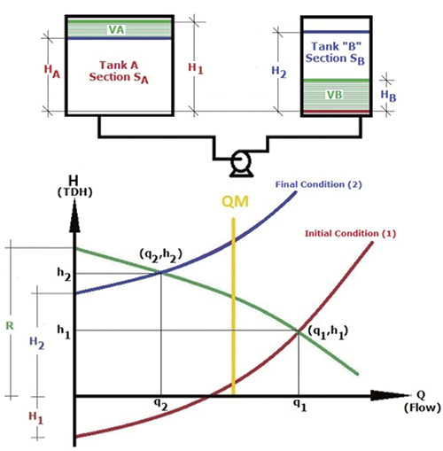 Figure 1. Typical transferring process
- They are commonly the first choice for moving water-like fluids. PD pumps are usually considered when the fluid is viscous.
- They are a well-known technology and familiar to most operators.
- They are believed to have a lower initial cost than PD pumps. However, this is not necessarily the case.
- Mechanical issues—Caused by vibration, which may reduce mechanical seal life, during off-BEP operation
- Overheating—Caused by low-flow operation
- Product leakage along the pump shaft—Because of shaft deflection (overhung impellers)
- Dry running—Can cause pump problems but may result in a catastrophic failure for a magnetically driven pump because the pumped media lubricates it
- Inability to strip lines
- Inability to self-prime
- Susceptibility to cavitation—Can occur because of entrained gases
- Fluid-handling capabilities affected—Can be compromised with changes in fluid viscosity, which can occur because of modifications and adjustments in the process or temperature changes
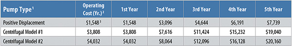 Table 1. Real-world example of the total cost of operation for a PD pump versus two centrifugal pumps
Notes:
1. Pump types compared are PD sliding vane and ANSI centrifugal.
2. Yearly operating cost is based on 3,000 hours of operation at a rate of $0.1 per kilowatt hour, or $223 per pump horsepower.
3. These costs are based on pumping an aqueous solution with a specific gravity of 1 at 300 Saybolt seconds universal at 126 gallons per minute (gpm) at 80 psig for the PD pump and a range of 114 gpm at 190 feet to 130 gpm at 165 feet for the centrifugal pumps (see Figure 2).
Table 1. Real-world example of the total cost of operation for a PD pump versus two centrifugal pumps
Notes:
1. Pump types compared are PD sliding vane and ANSI centrifugal.
2. Yearly operating cost is based on 3,000 hours of operation at a rate of $0.1 per kilowatt hour, or $223 per pump horsepower.
3. These costs are based on pumping an aqueous solution with a specific gravity of 1 at 300 Saybolt seconds universal at 126 gallons per minute (gpm) at 80 psig for the PD pump and a range of 114 gpm at 190 feet to 130 gpm at 165 feet for the centrifugal pumps (see Figure 2).
The Solution
Unlike centrifugal pumps, the design of PD pumps allows them to produce a constant flow at a given speed regardless of discharge pressure, which is critical in chemical manufacturing, which require precise dosing rates. Specifically, two pump types are ideal for chemical fluid transfer applications: sliding vane and eccentric disc. Sliding vane pumps feature a series of vanes in the pump rotor that slide out as they wear, which means that the pump delivers volumetric consistency throughout its life or until the vanes require replacement. Sliding vane pumps also offer zero shaft leakage (magnetic coupling); non-galling operation, stainless steel or ductile iron construction for corrosive liquids; chemical-duty mechanical seals; low-to-medium shear and agitation; and self-priming and dry-run capabilities, even in an explosive or hazardous environment. This pump type features a disc inside a pump cylinder. The disc is driven by an eccentric bearing on the pump shaft. This creates four distinct pumping chambers that increase and decrease in volume as the disc is rotated by the eccentric bearing, producing suction and discharge pressures as the chambers move in pairs that are 180 degrees apart. This operation ensures that the fluid passes through the pump at a constant and regular flow rate and eliminates pulsation within the pumped fluid. Because the pump does not depend on clearances to facilitate product flow, any slip or loss in volumetric efficiency is negligible. Additionally, with the mechanical sealless option, products that are difficult to seal and prone to crystallization cannot adhere to any surfaces and cause damage, which eliminates a maintenance concern. Figure 2. Combined operation
- Constant flow across the required range of pressures
- Low-shear operation, important when handling many raw materials in chemical production
- Dry-run capability and ability to strip discharge lines
- Ability to work to some levels with compressible fluids
 Equation 1
Where:
SA and SB = the areas of source Tank A and destination Tank B, respectively.
Volume VA = Volume VB is the amount of fluid transferred.
H1, H2, R = the points where the curves intercept the “H” Axis (Q = 0, or zero flow), which are known for a given system
H1 and H2 = static heads geometrically defined
R = a characteristic of the pump curve
HA and HB = the final condition at a given variation in time of h
tf = the time that the PD pump operates to deliver the same amount of fluid as the centrifugal pump while operating in a range
Equation 1
Where:
SA and SB = the areas of source Tank A and destination Tank B, respectively.
Volume VA = Volume VB is the amount of fluid transferred.
H1, H2, R = the points where the curves intercept the “H” Axis (Q = 0, or zero flow), which are known for a given system
H1 and H2 = static heads geometrically defined
R = a characteristic of the pump curve
HA and HB = the final condition at a given variation in time of h
tf = the time that the PD pump operates to deliver the same amount of fluid as the centrifugal pump while operating in a range