
Pump System Improvement
Engineered Software Inc.
05/18/2017
First of Two Parts I am often asked about the best way to arrive at a design point for pump selection. First, it is necessary to understand how the pump elements will interact with the processes and control elements. When all the elements of the piping system are working together, the system will meet its design requirements while minimizing the total lifetime costs. In this two-part series, we will look at a simple system consisting of a collection tank, a pump, distribution tank and the interconnecting piping as shown in Figure 1. This simple system is often used for distribution of water, bulk materials transfer, industrial waste collection and agricultural irrigation.
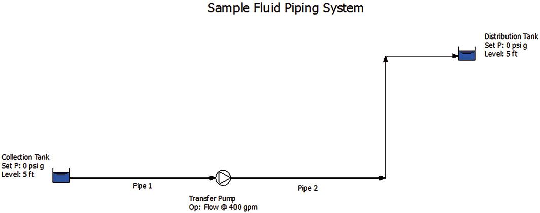 Figure 1. System showing the three principal elements found in every piping system. We will size the system elements to meet the system’s design requirements. (Courtesy of the author)
Designing the System
When creating a piping system, the first step is to understand the design requirements that must be met. Once this is done we can size the process equipment, determine the method of control and select the pumping equipment. After all the systems are completed, the plant is ready to come online.Design Requirement of the Drain Collection System
The function of the example system is to collect floor drains around the plant and send them to a waste treatment system where the water can be reused. After the fluid from floor drains flows into the collection tank by gravity, the transfer pump moves the fluid to the distribution tank. The distribution tank provides a constant source of fluid to the plant’s waste treatment system. The floor drains have water at 80 F, and it must be processed prior to reuse within the plant or release to the environment.System Requirements
Based on the projected plant operation, the flow collection system must be sized to handle a maximum flow rate of 400 gallons per minute (gpm). Since the flow collection system is open to atmosphere, we have sufficient system requirements to begin our system design.The Process Elements
We will look at the tanks first. The collecting tank capacity was sized to accept the design flow rate for 30 minutes, so the tank was sized for 12,000 gallons. The foundation for the tank can be determined based on the capacity and the weight of the full tank. The weight of the tank and the available space within the plant will be used to determine the location and elevation of the collection tank. In this example, the tank elevation is 100 feet above the plant datum. The size and elevation of the distribution tank is based on the needs of the capacity of the plant’s waste treatment system. The elevation and location of the distribution system has been determined by the needs of the waste treatment system. As a result, the elevation of the distribution tank is established at 120 feet. The elevation of the collection and distribution tank is used in determining the system’s static head. The change in tank elevation is 20 feet. To account for the difference in the tanks’ liquid levels, the level in the collection tank will be set to the lowest possible level of one foot, and the level in the distribution tank will be set to the highest possible level of 12 feet. As a result, the static head of the system is 20 feet plus 11 feet, or 31 feet in total. Based on the plant’s pipe specifications, the pipe material used in the waste collection system will be steel schedule 40 pipe. Using the design flow rate of 400 gpm and the sizing velocity guidelines found in the pipe specification, a 4-inch diameter pipe was selected. The head loss in the pipeline can be determined based on the estimated distance between the collection and distribution tank. The number and type of check valves and isolation valves can be selected to allow for proper system operation and maintenance. Since the pipe routing has not been established, the number of elbows used for head loss calculations for the pipelines can be estimated. The pump may now be selected with the given flow rate and by adding the systems static and dynamic head loss together.The Control Elements
Since this is a relatively simple system, the control elements will be based on the level in the collection tank. The pump will automatically start on a high level in the collection tank to prevent overflowing the tank. The pump will automatically stop on a low tank level to prevent the pump from running dry.The Pump Elements
Based on the design flow rate of 400 gpm and the sum of the process elements static head and dynamic head, a design point can be used for pump selection. Based on the user’s requirement, a submersible sump pump will be used in this application. Using the design point, the pump supplier can determine a specific pump and motor size to meet the needs of the waste collection system.Wrapping up the System Design
The necessary equipment can be ordered and installed within the plant now that the process, control and pump elements have been designed. Once the construction is finished on the waste collection system, it can be placed in service. This process is followed on most systems based on previous designs. Each of the elements in the system is controlled by specific engineering disciplines. The process group determines the type of process and capacity of the entire plant. The civil department determines the plant’s footprint, plus the structural support and locations for large equipment and tanks. The mechanical departments determine pipe sizing and routing needed to connect the equipment in the system. The mechanical department may also determine the design requirements for pump selection. The controls department typically determines the required instrumentations and method of controls. This process has been in use for years, and there was no better option. The entire system could only truly be examined comprehensively when the plant was placed into operation. Because of this, initial startup could uncover many costly problems within the plant’s design, delaying any return on the investment. This could have been prevented through a thorough analysis using simulation software. In next month’s column we will look at ways to simulate the operation of the entire system during the design process and what can be done to improve the simulation.For more Pumps System Improvement columns, click here.
