Slurry pumps have the difficult tasks of resisting wear while passing large particles and rocks, preventing air derating when pumping froth and foam, and remaining easy to maintain. This balancing act makes the slurry pump less efficient than its clean and gray water counterparts. The ability to pass large rocks is often achieved by limiting the number of thick vanes that would block the eye of the impeller. Many dredge and slurry pumps use three or four vanes and less commonly five vanes. These designs can leave large areas at the tip diameter at which the flow can slip and recirculate. This causes a loss of head. To control slip and reduce recirculation in slurry pumps, impellers with alternating primary and secondary vanes were invented in 1994. Originally developed in Canada (Canadian Patent Application CA2120977A1), these impellers are considered prior art to patents obtained in 2013 by different manufacturers (patents EP2310689A1, EP2331227A1, US8511998, WO2009143569A1). For example, the impeller in Figure 1, developed in 1994 under a grant from the National Research Council of Canada, features alternating principal and secondary vanes, or split vanes, for a vertical froth pump. These alternating vanes can break up air locks that result from entrained air associated with flotation froth for mineral processing circuits.
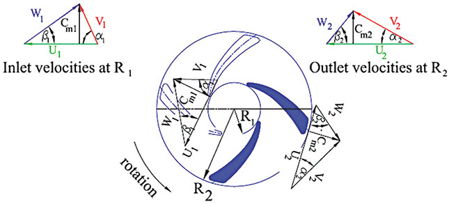 Figure 1. Velocity diagram through an impeller2 (Graphics courtesy of Splitvane Engineers Inc.)
The Ideal Euler Head
The flow through a centrifugal impeller is fairly complex, so mathematicians have developed a model based on velocity. Consider flow through a centrifugal pump impeller between two radii, R1 and R2 (see Figure 1). If a pump impeller rotates at an angular speed ω (in radians per second), it develops a tangential or peripheral velocity at the start radius of the vane (R1). Equation 1: U1 = R1ω It also develops a tangential or peripheral velocity at the tip radius of the vane (R2) (see Equation 2). Equation 2: U2 = R2ω The liquid passes through the impeller at a meridional velocity (Cm) that is perpendicular to the peripheral velocity (U) at each point. The meridional velocity depends on the free passage area between the vanes. At each radius, an angle (β) is defined as the angle between the center curve of the vane and the tangent to the radius. The component of velocity is in the direction of β and is called the relative velocity (W). The relative velocity and the peripheral velocity combine at each point to form the absolute velocity. As the fluid passes from the vane inlet R1 to the vane tip R2, head develops. The ideal head value is called the Euler head (see Equation 3 below). In Figure 1, W = Cm* cot β. The Euler head is modeled in terms of the following changes of energy:- (V22 – V12) = change in absolute kinetic energy
- (W22 – W12) = change in relative kinetic energy
- (U22 – U12) + (W22 – W12) = change in static energy through the impeller
 For slurry pumps, the value of β1 at the tip diameter of the eye of the impeller is between 14 and 30 degrees. The value of β2 at the tip diameter of the vanes is typically between 25 and 35 degrees. For particularly viscous mixtures, β2 may be as high as 60 degrees.2
Most pumps have a discharge angle β2 that is less than 90 degrees and are called impellers with backward curved vanes.
For slurry pumps, the value of β1 at the tip diameter of the eye of the impeller is between 14 and 30 degrees. The value of β2 at the tip diameter of the vanes is typically between 25 and 35 degrees. For particularly viscous mixtures, β2 may be as high as 60 degrees.2
Most pumps have a discharge angle β2 that is less than 90 degrees and are called impellers with backward curved vanes.
Slip of Flow Through the Impeller
The ideal Euler head would require multiple vanes to direct the flow correctly, but the shape and number of the vanes prevent the flow from achieving the ideal velocity diagram. As the real velocity diagram lags behind the ideal diagram, slip develops (see Figure 2).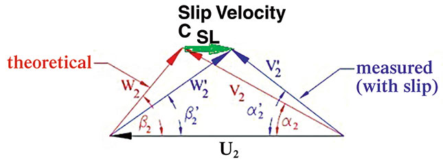 Figure 2. Ideal and practical velocity diagram
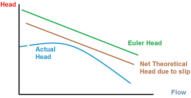 Figure 3. Euler head, net theoretical head and actual head developed by an impeller9
 The meridional velocity is not affected by slip.
The slip velocity develops as a result of the difference between W2 and W2’.
The actual head developed by the impeller at the best efficiency point can be related to the Euler ideal head through the hydraulic efficiency (ηH) and the slip factor (σ).6
Equation 6: H = ηH σHE
The authors of Reference 9 prefer to differentiate between the Euler theoretical head and net theoretical head (see Equation 7).
Equation 7: Hnth = σHE
The meridional velocity is not affected by slip.
The slip velocity develops as a result of the difference between W2 and W2’.
The actual head developed by the impeller at the best efficiency point can be related to the Euler ideal head through the hydraulic efficiency (ηH) and the slip factor (σ).6
Equation 6: H = ηH σHE
The authors of Reference 9 prefer to differentiate between the Euler theoretical head and net theoretical head (see Equation 7).
Equation 7: Hnth = σHE
References
- Abulnaga, B.E. (1994) – Patent Application CA2120977. Impeller with alternating primary and secondary vanes of different geometry. Filed November 11, 1994 – Filed in Canada.
- Abulnaga, B.E. (2002) – The Slurry Systems Handbook – McGraw-Hill 2002 – N.Y.
- Abulnaga, B.E. (2004) Pumping Oil Sand Froth, March 2004. 21st International Pump Users Symposium, Baltimore, Maryland. Published by Texas A&M University, Texas.
- Cherakassky V.M. 1977 – Pumps, Fans, Compressors – Mir Publications – Moscow.
- ANSI/HI 12.1-12.6 - Rotodynamic (Centrifugal) Slurry Pumps – 1st Edition.
- Jekat W.K. 1992 – Centrifugal Pump Theory – Section 2.1 of Karassik I.J., Krutzch W.C. Fraser.
- W.H. and Messina J.P. The Pump Handbook, Second Edition. McGraw-Hill – 1985.
- Wessner F.J.1967. A Review of Slip Factors for Centrifugal Impellers – Transactions of ASME. pp. 558-572.
- Thin K.C., M.M. Khaing and K.M. Aye – 2008 – Design and Performance Analysis of Centrifugal Pump – World Academy of Science, Engineering and Technology – Vol 2:2008. pp. 10-22.