Although the traditional application is as a bearing surface, the technology is suitable for a seal face surface in pumps.
Flowserve

A common theme in sealing pumps is to adapt existing mechanical seals to the application. An example is taking non-cartridge component seals and making them into cartridge seals, or taking single seal designs and placing them in series to create dual seals. This practice can result in a seal design that is not optimized for the intended service.

Vertical Sump Pump Diagram
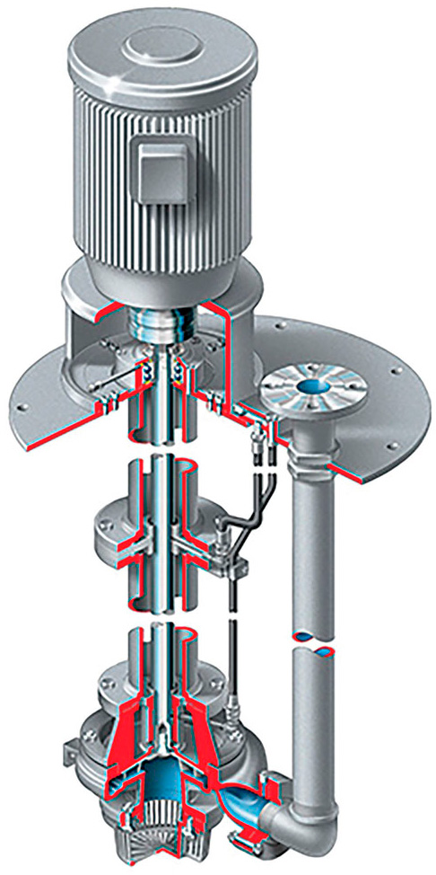
Figure 1. Cutaway of a typical vertical sump pump (Images and graphics courtesy of Flowserve)

Many industries have come to rely on the guidance of mechanical seal standard American Petroleum Institute (API) 682, which provides qualification standards for reliably sealing the majority of pumps within industrial plants, specifically oil refineries.

Like a standardized test in grade school, there is a tendency for mechanical seal manufacturers to “teach to the test,” creating seal models that align with the descriptions and qualification test requirements in the industry standard. This practice becomes problematic when attempting to fit equipment that includes unique seal chamber conditions with a general-duty, API 682-compliant design.

The Outlying Equipment

There are many pieces of equipment that require seals but are not well-covered by any sealing industry standard. As a result, their needs can be overlooked. Examples of plant specialty equipment include screw conveyers; blenders, mixers and agitators; rotary valves; and vertical sump pumps. This challenge affects vertical sump pump applications, which have a distinct seal chamber environment compared to its pumping peers.

The vertical sump pump is found throughout industrial plants in open and closed sumps. Because these pumps feature side discharges to transport pumped fluid, the shaft column is effectively dry, with only some liquid lubrication for line shaft bearings. The seal chamber, which is near the mounting plate, creates the vapor-proof seal when the pump is installed in closed sumps.

The vertical sump pump is described in the oil and gas standard for pumps, API 610, where it is given the designation of pump type VS4. It is notable that there is no API 682 qualification test that duplicates the dry sealing environment in these pumps, and API 682 provides no specific guidance to applying seals in VS4 pumps. This makes API 682 qualification status largely immaterial for demonstrating suitability for these pumps.

Seals for VS4 Pumps

Pumps installed in open sumps have little need for a vapor-tight seal about the pump shaft, but closed sumps often contain dangerous vapors that cannot be permitted to vent into the atmosphere.

The most basic sealing options include lip seals and packing, which may be optionally purged with nitrogen gas to reduce emissions.

Porous Media Gas Seal
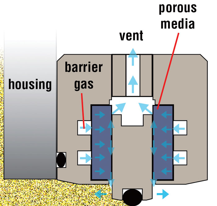
Figure 2. Illustration of porous media gas seal operating principles

Performance can be further improved with a dry running containment mechanical seal. The highest level of emissions prevention is attained only with a dual pressurized mechanical seal. These can operate on either gas or liquid barrier fluid.

The vertical sump pump situation is representative of a larger group of low-pressure, dry seal chamber applications, which require either zero process emissions or mechanical seals supported by an external fluid. With dry seal chambers, the natural solution is to apply a dry running gas seal; however, because this equipment has historically been sealed with lip seals or packing, the area available for the seal is normally confined, making it difficult to apply traditional dual seals.

In order to create a more compact solution, a seal manufacturer partnered with a leading manufacturer of porous media air bearings for the precision machine tool, semiconductor and metrology industries. Although the traditional application of porous media technology was as a bearing surface, the technology is suitable for use as a seal face surface.

Acid duty sump pump with porous media gas seal installed.Image 1. Acid duty sump pump with porous media gas seal installed.

Porous media works by directly injecting a barrier gas into the sealing interface through a ring of porous carbon. Traditional gas seals pump gas across the sealing interface from the inner or outer diameter. By directly injecting barrier gas into the sealing interface, it becomes possible to create a true zero-emissions seal with a single pair of seal faces. This achieves dual-seal performance in a single seal, which reduces the seal’s overall size.

The first mechanical seal created using porous media technology has two sets of seal faces which locate and align the rotor. The inner seal faces alone create the zero-emissions seal. These seals operate on a thin film of gas without contact or wear, making them exceptionally reliable.

By eliminating the complication of flexible springs or metal bellows, the seal maintains a short axial length, typically less than two inches (50 mm), regardless of the shaft size. Additionally, porous media enables the seal to handle reverse rotation, which can occur when a pump is unexpectedly shut down.

In the Field

Pumping acid in a chemical plant proved to be an ideal application for the porous media gas seal. The chemcial plant was using nitrogen-purged packing, but continued to experience downtime because of packing failures approximately every nine to 12 months.

Porous media gas seal in secondary containment shell installed in vertical sump pump
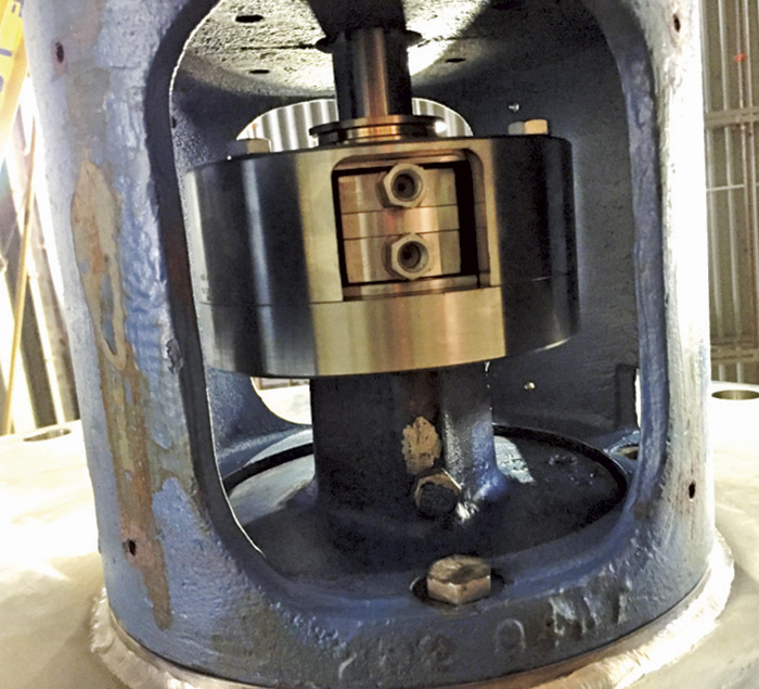
Image 2. Porous media gas seal in secondary containment shell installed in vertical sump pump

Packing failures were preceded by ever-increasing nitrogen purge gas consumption, which affected the operating cost and foretold the upcoming packing failure. Failure was determined when either the nitrogen consumption reached an intolerable level or when the packing could no longer hold back the pressure in the pump column.

The cutaway of a porous media seal illustrates its design simplicity and shows the porous carbon seal faces.
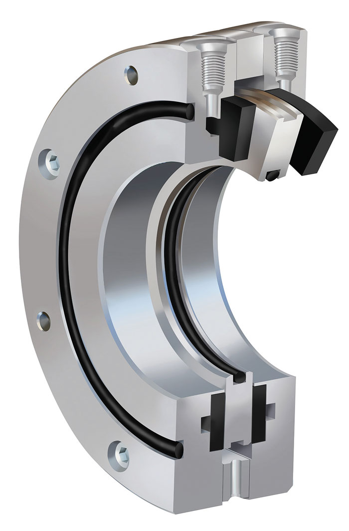
Image 3. The cutaway of a porous media seal illustrates its design simplicity and shows the porous carbon seal faces.

A high-duty, dual pressurized gas seal was an option, but the cost was excessive, considering the low-duty conditions near atmospheric pressure and no direct contact between the seal and liquid acid.

The porous media gas seal was available with a secondary containment shell and met the customer’s budget. It was selected and installed in a spare pump and stored at the customer’s site.

When the installed pump failed, the spare pump was installed and started. The user was pleased with the new seal’s reduced nitrogen purge gas consumption and its zero-emissions performance.

The seal continued to perform well six months later, with no change in barrier gas consumption or signs of distress. The facility has ordered an additional porous media gas seal and intends to stick with this new sealing solution for these services.

Conclusion

For each pumping or fluid transport application, an appropriate sealing solution should exist. While horizontal overhung and between-bearings pumps command the attention of plant operators, it can be costly to apply the same seals appropriate for those pumps in a plant’s specialty equipment.

Porous media technology offers a new approach to zero-emissions gas sealing in a compact package, with robustness to loss of gas pressure and a simplicity of design.

Issue