
Q. Our pumps take their suction from an open tank. When the liquid level drops, surface vortices are formed that allow air to be drawn into the pumps. What changes can be made to the tank to correct this problem?
A. Undesirable flow conditions may be created at the pump inlet in the tank depending on the inflow-outflow arrangement in a storage tank, whether the tank inflow is operating while the pump suction (inlet) is operating, and whether flow obstructions exist in the tank. Even if only the pump inlet is operating and there are no flow obstructions in the tank, the non-uniform approach flow to the pump inlet may cause pre-swirl and vortices.
Since a dry-pit pump is usually located some distance downstream from its piping inlet in the tank, the effect of these flow disturbances on the pump is not as severe as with wet-pit pumps. For example, local flow separation, swirl or velocity non-uniformities, although creating greater head losses at the inlet, may be dissipated in the approach piping to the pump. The main problem is usually entrainment of air (or other tank gases) due to free-surface vortices, as this air may collect in the piping (causing air binding) or cause pump performance degradation.
Preventing the formation of free-surface vortices at tank inlets to pumps allows the tank to be drawn to lower levels than would otherwise be possible. This benefit requires the use of various anti-vortex devices at the inlet. Some common types of such devices are shown in Figure A.12.
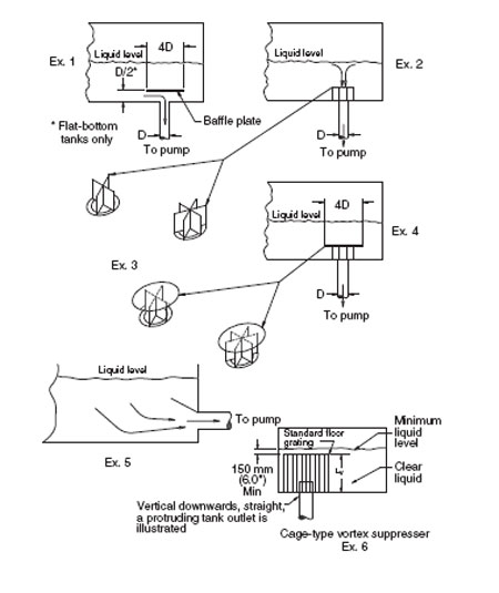
Figure A.12. Anti-vortex devices
As an alternative, a cage type vortex suppressor may be used, as illustrated in Figure A.12, example 6.
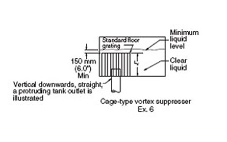
Figure A.12. Example 6
The cubic cage may be made of standard 38 mm (1.5 in) deep (or deeper) floor grating (or its equivalent). The length, width and height of the cubic cage, each with a characteristic length termed Lv, should be about 3 inlet pipe diameters, and the top of the cage should be submerged about 150 mm (6 in) below the minimum liquid level. Non-cubic cage shapes are also effective if the upper (horizontal) grating is at least 3 inlet pipe diameters on each side and is also submerged 150 mm (6 in) below the minimum liquid level. A single horizontal grating meeting these guidelines may also be effective.
Tests on such cage type vortex suppressors have demonstrated their capability to reduce air entrainment to nearly zero even under adverse approach flow conditions (Padmanabhan, 1982). However, it may be noted that the minimum submergence from the tank floor is dictated by the vertical cage dimension plus the needed 150 mm (6 in) submergence above the top of the cage.
Q. Ball bearing failure is a chronic problem in our plant's pumps. What can be done to reduce these failures and improve the MTBR?
A. A leading cause of ball bearing failures is often lubricant contamination. To improve lubricant quality, frequent monitoring of the lubricant is necessary.
Lubricant analysis is designed to measure three things:
- Wear rates of bearings or bearing housing face seals
- Lubricant contamination levels
- Lubricant degradation
It is useful for monitoring a lubricant's condition as a precursor to bearing or face seal failure.
The following sections are intended to make it easy to understand the basics of what the tests measure and how to use that information.
A. Measuring Metal Particles from Wear
Several techniques for measuring metal particles and evaluating wear mechanisms are available in the industry today.
Generally, laboratories perform a spectrographic analysis consisting of up to 21 different metallic elements. These elements cover most, if not all, inorganic additives, contaminants and wear metals. A spectrographic analysis indicates the presence of metallic elements, but not the amounts. Quantitative evaluations are obtained from particle counting analyses. A particle counting analysis will provide information on the number of particles in a sample within various size ranges and an analysis of the contaminants. A description of the methods and codes used can be found in ISO 4402 and SAE ARP 598. Lubricant analysis laboratories are also a good information source.
Some wear on metal parts, although not desirable, can be considered normal. Large amounts of metal contaminants usually indicate a serious machine problem. Different machine parts are made from different metals, so the presence of particular metals indicates which components are wearing. Common wear metals are iron, aluminum, chromium, copper, lead, tin, nickel and silver.
B. Evaluating Wear Rates
The accurate diagnosis of wear rates can be accomplished through the use of an ongoing lubricant analysis program where the data has been trended over a period of time, accompanied by periodic machine inspection and wear documentation.
When no historical data are available for a machine and/or no other like machines exist in the database, an experienced data evaluator may review the laboratory data and make a value judgment about the wear situation of a specific sample.
When there are multiple machines of the same type, and/or when a machine has been sampled several times, data can be trended. Samples that have metallic content that is increasing at an unusually high rate or data that are statistically out of the normal range indicate a problem with the machine.
The lubricant analysis should also measure certain metallic elements found as additives in the lubricant. The primary purpose of analyzing for the additives is to ensure that the appropriate additives are present and that no other inorganic additives indicate cross-contamination has occurred. Performing an analysis on the fresh unused lubricant will show which additives are there. Subsequent oil samples can be compared to this baseline.
Common additive metals are boron, zinc, phosphorus, calcium, barium, magnesium, molybdenum and sulfur.
C. Measuring Lubricant Contamination
Lubricating oil must be physically clean and chemically suitable to properly lubricate equipment. Contamination is commonly classified as organic or inorganic.
D. Organic Lubricant Contamination
Organic contamination can be from the byproducts of lubricant degradation or from external sources. Most often, it is from lubricant degradation. If the organic contamination is from an external source, it is usually inherent to the operation and readily identifiable like chlorinated hydrocarbons, process liquids, acids, diesel fuel, glycol or freon. Organic contamination can increase or decrease the lubricant's viscosity. The analyses most often performed to measure organic contamination are viscosity, acid number, infrared analysis and flash point.
E. Inorganic Lubricant Contamination
Contaminants in the oil like dirt, dust, welding slag, etc., can be carried throughout the machine and cause severe abrasive wear.
- Dirt and abrasives-Dirt and abrasives generally enter the machine through poor housekeeping practices or systems that are not properly sealed from the environment. Another source of the element silicon can be found in sealant and anti-foam additives.
- Fibers and debris-Debris in general is considered an inorganic contaminate. Debris can be found in the form of fibrous materials such as rags or filter media breakdown. A variety of laboratory techniques measure "solid, inorganic" contamination. The most common method for measuring the concentration of these contaminates without regard for the actual make-up of the debris is an automatic particle counting instrument.
- Water-Water is one of the most common contaminates found. It is the easiest to detect in large quantities. Water can come from internal sources such as leaks in cooling systems and condensation or external sources such as leaking seals. Usually, the lubricant turns white in color and emulsifies.
F. Measuring Lubricant Degradation
Degradation characteristic of lubricating oils can be measured through viscosity, acidity or antioxidant levels.
Measurable changes in viscosity or acidity are generally considered to be condemning limits for a lubricant, while the antioxidant level acts as an early warning device for lubricant changes. Antioxidants are added to lubricants to protect the base oil from oxidizing. When these additives are "used up," the base oil is left unprotected and degrades at an accelerated rate allowing the formation of oxidation byproducts harmful to the machine. As the antioxidant nears total depletion, the viscosity and acid number dramatically increase.
G. Lubricant Sampling Techniques
Acquiring a representative lubricant sample is extremely important to the overall success of a lubricant analysis program. Sampling points should be on the discharge side of the operating unit before the filter.
In non-circulating sumps, samples should be taken while the pump is operating (or immediately after shutdown) to ensure well-mixed lubricant is obtained. Samples should be withdrawn from within 12 mm (0.5 in) of the surface of an oil sump. A sample from the bottom of the sump will indicate the presence of free water. A variety of sampling techniques can be used. Contact the laboratory for more information on special situations.
Pumps & Systems, March 2010
