


Pumps and Systems, February 2007
When evaluating bearing distress, the babbitted shoe surface is commonly the only area that is examined. Although a great deal of information can be extracted from the babbitt appearance, additional information exists elsewhere.
These "secondary sources" of diagnostic information often prove to be very valuable, since the babbitted surfaces are usually destroyed in a catastrophic bearing failure. Even a bearing wipe, which is the most common appearance of distress, may hide valuable information.
The "textbook" cases of distress modes are especially useful in diagnosing problems prior to the damage that occurs when a bearing can no longer support an oil film. Through the prudent use of temperature and vibration monitoring equipment, routine oil analyses, lubrication system evaluations and machine operational performance reviews, bearing distress may be identified and evaluated before catastrophic failure occurs.
Bearing health is commonly monitored through the use of temperature measurements. Be aware that temperature sensors may be mounted in a wide variety of locations, with a corresponding variation in temperature. The specific location and type of sensor must be known in order for the measured temperature data to have any real value.
Beginning An Evaluation
To start, the bearing assembly should be completely disassembled so that all of the bearing components may be evaluated. Do not clean the bearing, since valuable information may be lost.
 |
| Figure 1. Thrust and journal bearing part schematic . |
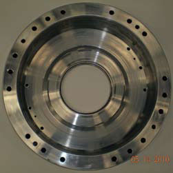
Base Ring
Examine the base ring. During routine operation, the lower leveling plates may form indentations in the base ring, on either side of the dowels that locate them. The indentations should be identical and barely noticeable. Deep, wide indentations are an indication of a high load. The rocking strip on the bottom of the lower leveling plates contacts the base ring, and its condition presents another indication of bearing load.
The cleanliness of the bearing and oil can also be determined, since deposits are often trapped in the base ring. Evidence of water contamination, particularly in vertical machines, may go unnoticed unless the base ring is examined.
Leveling Plates
The spherical pivot in the rear of each thrust shoe rests in the center of a flat area on the hardened upper leveling plate. This flattened area is susceptible to indentation due to the point contact of the pivot. The indentation is easily identified by a bright contact area. This area indicates where the shoe operates on the upper leveling plate, and its depth gives an indication of load. Close examination of the upper leveling plate near the contact area may also produce evidence of electrical pitting.
The upper leveling plates interact with the lower leveling plates on radiused "wings." The upper leveling plates are typically hardened; the lowers are not. When new, the leveling plates have line contact. There is little friction between the wings, and the bearing can react quickly to load changes. Depending on the nature and magnitude of the thrust load, the wing contact areas will increase in time. The contact region of the wings, again noted by bright areas, will normally appear larger on the lower leveling plates. If the rotating collar is not perpendicular to the shaft axis, the leveling plates will continuously equalize, causing rapid wear.
Shoe Support
The shoe support is the hardened spherical plug in the rear face of each thrust shoe. Based on the magnitude and nature of the thrust loads, the spherical surface will flatten where it contacts the upper leveling plate. The contact area will appear as a bright spot on the plug. If evidence of hard contact exists (a large contact spot), rest the shoes (pivot down) on a flat surface. If the shoes do not rock freely in all directions they should be replaced.
The pivot can also appear to have random contact areas, indicating excessive end play, or it may be discolored, indicating lack of lubrication.
Shoe Body
The shoe body should be periodically examined for displaced metal or pitting. Indentations routinely occur where the shoe contacts the base ring shoe pocket in the direction of rotation. Displaced metal exhibiting a coarse grain may indicate erosion damage; bright or peened spots may indicate unwanted contact. Depending upon the shape of the individual pits, pitting may indicate corrosion or undesirable stray shaft currents.
Shoe Surface
When evaluating the shoe surface, the first step should be to determine the direction of rotation. This may be accomplished by evaluating:
- Abrasion scratches
- Discoloration (75-75 location)
- Babbitt flow
- Babbitt overlay
- Thrust shoe/base ring contact
Use caution when evaluating babbitt overlay (babbitt "rolled over" the edges of the shoes), since it may appear on both the leading and trailing shoe edges.
Normal
A healthy shoe will exhibit a smooth finish, with no babbitt voids or overlays. The dull grey finish of a brand new shoe may remain unchanged after many hours of operation, or it may appear glossy in spots or in its entirety. Routine thermal cycling of the bearing may cause the emergence of a mild "starburst" or mottled
$1 in the babbitt. This is harmless, providing the shoe is flat and cracks do not exist.
Abrasion
A bearing surface exhibiting circumferential scratches is the result of abrasion damage (see Figure 2). Abrasion is caused by hard debris, which is larger than the film thickness, passing through the oil film. The debris may embed itself in the soft babbitt, exhibiting a short arc on the shoe surface, ending at the point the debris becomes embedded. Depending on the debris size, the scratch may continue across the entire shoe surface.
 |
| Figure 2. Thrust shoe surface abrasion. |
Abrasion damage becomes worse as time progresses. Surface scratches allow an escape for lubricating oil in the oil wedge, decreasing the film thickness. This will eventually lead to a bearing wipe.
Another source of abrasion damage is a rough journal, collar or runner surface. Roughness may be due to previous abrasion damage. It may also be from rust formed after extended periods of down time. New bearings should not be installed when the rotor is visibly damaged.
Random scratches, which may run a staggered path both circumferentially and radially, are more likely to appear in the unloaded bearing or unloaded portion of the bearing. In a thrust bearing, it may indicate excessive end play (axial clearance). Random scratches may also indicate careless handling at installation or disassembly.
To eliminate abrasion damage, the lubricating oil must be filtered. If the oil cannot be filtered or has degraded, it should be replaced. It is important to evaluate the filtering system, since the problem may be an incorrectly sized filter. The filter should only pass debris smaller in size than the predicted bearing minimum film thickness.
In addition to filtering/replacing the oil, the entire bearing assembly, oil reservoir and piping should be flushed and cleaned. The original bearing finish should also be restored. Journal shoes typically must be replaced, but if the correction leaves the bearing within design tolerance, the bearing may be reused.
Although the babbitted surface is usually damaged more severely, the rotating collar or journal surface must also be evaluated. Debris partially lodged in the babbitt may score the steel surfaces. These surfaces must be restored by lapping or hand stoning.
Discoloration
Tin Oxide Damage
This is one of several electrochemical reactions which eliminate the "embedability" properties of a fluid-film bearing. Tin oxide damage is recognizable by the hard, dark brown or black film that forms on the babbitt (see Figure 3).
 |
| Figure 3. Tin oxide damage. |
Tin oxide forms in the presence of tin-based babbitt, oil and salt water, beginning in areas of high temperature and pressure. Once it has formed it cannot be dissolved, and its hardness will prevent foreign particles from embedding in the babbitt lining. This damage may be stopped by eliminating some or all of the contributing elements. The lubricating oil must be replaced. A reduction in oil temperature may also discourage the formation of tin oxide.
In addition to replacing the oil, the entire bearing assembly, oil reservoir and piping should be flushed and cleaned with mineral spirits. The bearing shoes should be replaced. The condition of the rotating journal, collar or runner surfaces must also be evaluated. They must be restored to original condition, either by lapping, hand stoning or replacement.
Overheating
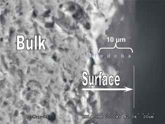
Overheating damage may represent itself in many ways, such as babbitt discoloration, cracking, wiping or deformation. Repeated cycles of heating may produce thermal ratcheting, a type of surface deformation that occurs in anisotropic materials (see Figure 4). These materials possess different thermal expansion coefficients in each crystal axis.
 |
| Figure 4. Thermal ratcheting. |
Oil additive packages may "plate out" at relatively high bearing temperatures. The plating typically begins in the area of highest temperature, the 75-75 location (see Figure 5).
 |
| Figure 5. Overheating, oil additives plated out. |
Overheating may be caused by numerous sources, many of which concern the quantity and quality of the lubricant supply. Among the possible causes are:
- Improper lubricant selection
- Inadequate lubricant supply
- Interrupted fluid film
- Boundary lubrication
The following conditions may also cause overheating:
- Improper bearing selection
- HP lift system failure
- Poor collar, runner or journal surface finish
- Insufficient bearing clearance
- Excessive load
- Overspeed
- Harsh operating environment
Verify that the quantity and quality of oil flowing to the bearing is sufficient. These values should be available from the bearing manufacturer.
If thermal ratcheting has occurred, examine the shoes for the existence and depth of cracks. Remove the cracks and restore the original shoe surface. If this cannot be done, replace the shoes. Journal shoes typically must be replaced, but if the correction leaves the bearing within design tolerance, the bearing may be reused.
The condition of the rotating journal, collar or runner surfaces must also be evaluated. It must be restored to original condition, either by lapping, hand stoning or replacement.
Voids
Electrical Pitting
Electrical pitting appears as rounded pits in the bearing lining. The pits may appear frosted (see Figure 6), or they may be blackened due to oil deposits. It is not unusual for them to be very small and difficult to observe with the unaided eye. A clearly defined boundary exists between the pitted and unpitted regions, with the pitting usually occurring where the oil film is thinnest.
 |
| Figure 6. Stray shaft currents/electrical pitting (frosting). |
As pitting progresses, the individual pits lose their characteristic appearance as they begin to overlap. Pits located near the boundary should still be intact. The debris that enters the oil begins abrasion damage. Once the bearing surface becomes incapable of supporting an oil film, the bearing will wipe. The bearing may recover an oil film and continue to operate, and pitting will begin again. This process may occur several times before the inevitable catastrophic bearing failure.
Electrical pitting damage is caused by intermittent arcing between the stationary and rotating machine components. Because of the small film thicknesses relative to other machine clearances, the arcing commonly occurs through the bearings. Although the rotating and other stationary members can also be affected, the most severe pitting occurs in the soft babbitt.
Electrical pitting can be electrostatic or electromagnetic in origin. Although both sources result in pitting damage, they differ in origin and destructive capabilities.
Electrostatic shaft current (direct current) is the milder of the two. Damage progresses slowly, and it always occurs at the location with the lowest resistance to ground. It can be attributed to charged lubricant, charged drive belts, or impinging particles. This type of shaft current can be eliminated with grounding brushes or straps. Bearing isolation is also recommended.
Electromagnetic shaft current (alternating current) is stronger and more severe than electrostatic current. It is produced by the magnetization of rotating and/or stationary components. This type of current will not always occur at the location of lowest resistance. Because the current is stronger, bearing damage is often accompanied by journal, collar or runner damage. Electromagnetic currents are best eliminated by demagnetizing the affected component. Grounding brushes or straps may or may not be helpful. The bearings should also be isolated.
The lubricating oil must be filtered or replaced. Pitting damage often blackens the oil and fills it with debris. In addition to filtering/replacing the oil, the entire bearing assembly, oil reservoir and piping should be flushed and cleaned. The original bearing finish should also be restored. Journal shoes typically must be replaced, but if the correction leaves the bearing within design tolerance, the bearing may be reused. The condition of the rotating journal, collar or runner surfaces must also be evaluated. It must be restored to original condition, either by lapping, hand stoning or replacement.
Fatigue
Fatigue damage may represent itself as intergranular or hairline cracks in the babbitt. The cracks may appear to open in the direction of rotation. Pieces of babbitt may spall out or appear to be pulled away in the direction of rotation. The cracks extend toward the babbitt bond line, and may reveal the shoe backing (see Figures 7-9).
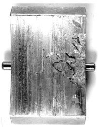 |
| Figure 7. Edge load pivoted shoe showing babbitt mechanical fatigue. |
 |
| Figure 8. Edge load journal shell with babbitt mechanical fatigue. |
 |
| Figure 9. Babbitt fatigue in a thin thrust plate. |
A combination of causes contributes to fatigue damage, but concentrated cyclic loading is usually involved. The fatigue mechanism involves repeated bending or flexing of the bearing, and damage occurs more rapidly with poor bonding. It is important to note that fatigue damage will occur without poor bonding. Fatigue can occur when conditions produce concentrated cyclic loads, such as:
- Misalignment
- Journal eccentricity
- Imbalance
- Bent shaft
- Thermal cycling
- Vibration
Performance data should be reviewed to determine if a vibration increase occurred. The leveling plate wings should be examined for signs of excessive wear, indicating the rotating collar or runner is not perpendicular to the shaft axis.
High bearing temperature may also be considered as a contributing factor to fatigue damage. As temperatures increase, the fatigue strength of bearing materials decreases.
The lubricating oil must be filtered or replaced. In addition to filtering/replacing the oil, the entire bearing assembly, oil reservoir and piping should be flushed and cleaned. Depending on the extent of damage, voids in the babbitt can be puddle-repaired. The original bearing finish must be restored. Journal shoes may also be puddle-repaired and refinished. If this cannot be done, the shoes must be replaced.
Although the babbitted surface is usually damaged more severely, the rotating collar or journal surface must also be evaluated. This surface must also be restored to original condition, either by lapping or hand stoning.
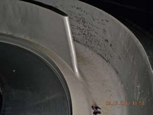
Cavitation
Cavitation damage appears as discreet irregularly-shaped babbitt voids which may or may not extend to the bond line. It may also appear as localized babbitt erosion. The location of the damage is important in determining the trouble source (see Figures 10-12).
 |
| Figure 10. Thrust shoe cavitation damage in babbitt face. |
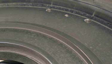 |
| Figure 11. Thrust shoe cavitation towards outside diameter. |
 |
| Figure 12. Cavitation damage on outside diameter of collar. |
Often called cavitation erosion, cavitation damage is caused by the formation and implosion of vapor bubbles in areas of rapid pressure change. Damage often occurs at the outside diameter of thrust bearings due to the existence of higher velocities. This type of damage can also affect stationary machine components in close proximity to the rotor. Based on its source, cavitation can be eliminated in a number of ways:
- Radius/chamfer sharp steps
- Modify bearing grooves
- Reduce bearing clearance
- Reduce bearing arc
- Eliminate flow restrictions (down stream)
- Increase lubricant flow
- Increase oil viscosity
- Lower the bearing temperature
- Change oil feed pressure
- Use harder bearing materials
The lubricating oil must be filtered or replaced. In addition to filtering/replacing the oil, the entire bearing assembly, oil reservoir and piping should be flushed and cleaned.
Depending on the extent of damage, voids in the babbitt can be puddle-repaired. The original bearing finish must be restored. Journal shoes may also be puddle-repaired and refinished. If this cannot be done, the shoes must be replaced.
Although the babbitted surface is usually damaged more severely, the rotating collar, runner or journal surface must also be evaluated. This surface must also be restored to original condition, either by lapping or hand stoning.
Erosion
Erosion damage may appear as localized babbitt voids with smooth edges, particularly in the direction of rotation. Damage is more likely to occur in stationary members.
As a rule of thumb, if the babbitt has been affected, the cause was cavitation damage, not erosion. Since erosion is caused by sudden obstructions in oil flow, it is more likely to occur in other areas, since the babbitt is under high pressure. Once damaged, however, babbitt erosion may occur. Corrective action is similar to that employed in eliminating cavitation damage, with the emphasis on streamlining oil flow through the bearing.
Corrosion
Corrosion damage is characterized by the widespread removal of the bearing lining by chemical attack. This attack produces a latticework appearance. The damage may be uniform with the affected elements being "washed away," leaving the corrosion resistant elements behind.
Corrosion may also affect the rotating collar, runner or journal, appearing as random, widespread rust or pitting. The pits are easily distinguished from electrical pitting, since they are not as uniform or smooth-bottomed. Corrosive materials may appear in the lubricating oil through:
- Decomposition of oil additives
- Acidic oxidation products formed in service
- Water or coolant in lube oil
- Direct corrosive contamination
Bearing housing seals, oil additive packages, and oil reservoir operating temperatures should be evaluated as an initial step in eliminating corrosion. The integrity of cooling coils should also be examined.
The cause of corrosion is best detected by knowledge of the babbitt composition and an oil analysis. Corrosion can be eliminated by replacing the lubricating oil. In addition, the entire bearing assembly, oil reservoir and piping should be flushed and cleaned. If the original bearing finish cannot be restored, the bearing must be replaced. The rotating collar, runner or journal surface must also be evaluated and restored to original condition, either by lapping or hand stoning.
Collar/Runner/Journal Surface
The most commonly overlooked bearing component is the collar. It is the single most important part of the bearing. Collar rotation draws oil into the region between the collar and shoe surfaces. Oil adheres to the collar and is pulled into pressurized oil wedges. This occurs due to the collar surface finish. If the collar finish is too smooth (better than 12-RMS), it will not move an adequate supply of oil; too rough, and the bearing shoes will be damaged. Ideally the finish should be between 12-RMS to 16-RMS.
Each time a bearing is inspected, the collar should be inspected and worked as necessary. Glossy areas on the collar can be easily removed by hand scrubbing with a soft 600-grit oilstone. Collars with significant operating time may have lost their original surface flatness. This flatness, as well as the surface finish, should be restored.
If a split runner is used, it should be separated into halves and evaluated. Relative motion between the halves will result in fretting damage to the runner, as well as potential cavitation-like damage to the bearing surfaces. It is very important that the collar faces be parallel, and perpendicular to the centerline of the shaft. If the collar is not within tolerance, the resultant "wobble" will force the shoes and leveling plates to constantly equalize, causing rapid leveling plate wear (see Figure 13).
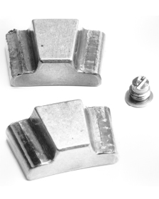 |
| Figure 13. Leveling plate wear due to collar wobble. |
Oil
A quick visual examination of the oil or oil filter may be all that is required to determine that a problem exists and that further investigation is necessary. Cloudy or discolored oil indicates that a problem exists.
A thorough oil analysis can provide very useful data to assist in diagnosing bearing or machine distress. Be aware that the usefulness of the analysis is directly related to the information you request. As a minimum, the following should be supplied:
- Particulate density
- Particulate breakdown
- Viscosity
- Water contamination
- Chemical breakdown
The amount of particulate, as well as its content, can identify potential trouble spots. Oil viscosity will decrease in time, and whether or not distress is suspected, it should be periodically evaluated. Water contamination is extremely unwanted since it can cause rust and oil foaming and, if it is drawn into the oil film, bearing failure. A chemical breakdown of the oil will help to determine the integrity of additive packages and the presence of unwanted contaminants.
Operational Data
Another important source of diagnostic information is unit operational data. Identifying periods of load or speed changes, recent maintenance, or the performance of related machinery may also help determine the root cause of distress. Vibration data or an analysis may help discover existing problems, as well as examining the remaining bearings in a troubled unit.
References
- Sohre, J.S., and Nippes, P.I., "Electromagnetic Shaft Currents and Demagnetization on Rotors of Turbines and Compressors," Proceedings of the Seventh Turbomachinery Symposium (1978).
Recommended Reading and References
- "Practical Machinery Management for Process Plants," Bloch & Geitner, Volume 2, Gulf Publishing Company.
- "Thermal Aspects of Fluid Film Tribology," Oscar Pinkus, ASME Press.
- "Theory and Practice of Lubrication for Engineers," by Dudley D. Fuller, Wiley & Sons, Inc.
- EPRI GS-7352 Project 1648-10 Final Report, "Manual of Bearing Failures and Repair in Power Plant Rotating Equipment," MTI.