Say goodbye to concerns about pump seizure: By properly applying composite materials to a troublesome boiler feed water pump, this large process facility in Alberta can now run one pump during full-rate operation with very low vibration and higher efficiency.
The reliability and efficiency impacts of close-clearance wear components - wear rings, inter-stage bushings, throat bushings, and pressure-reducing bushings - have been well documented.
In 1985, Bloch and Geitner cited the following potential problems associated with excessive wear ring clearance: efficiency losses, loss of rotor stability, shaft breakage, driver overloading, bearing overheating or failure, unequal load sharing in parallel pump operation, noise and damage typically associated with cavitation, and possible total pump destruction (p. 31-36).
One application for which the wear components are particularly important is boiler feed water. In the typical process plant, the boiler feed water pump is a multistage, horizontally-split, between-bearings design that is heavily dependant upon the wear components for rotor stability. Material selection is very important to ensure long-term reliability in this service.
The value of proper application and installation of modern composites is demonstrated by the results from a 9-stage boiler feed water pump from a large process facility in Central Alberta.
Why Wear Components are Important
The close clearance wear components in a centrifugal pump perform similar functions. They separate high pressure areas within the pump from lower pressure areas via a minimal clearance between a rotating and stationary member.
Due to the differential pressure across these components, there is substantial flow from the high pressure to lower pressure regions of the pump - recirculation flow. If inadequate clearance lies between two metal components, the rotating and stationary elements could possibly seize and lead to substantial pump damage (Bloch, 1988).
Conversely, as the clearance between rotating and stationary components increases, the recirculation flow within the pump increases and efficiency drops (Bloch and Geitner, 1985). Over time, this will become evident to the pump operators as recirculation flow increases to the point where the pump can no longer operate at design capacity.
What the operators may not notice is that the wear components also contribute substantially to rotor stability (Lobanoff and Ross, 1992, p. 440-451). Increased clearance at the wear components can lead to higher vibration, shorter bearing life, and the potential for high-energy failure modes such as shaft breakage.
Furthermore, recirculation flow at the first-stage impeller eye increases the effective inlet fluid temperature, possibly leading to cavitation damage (Lobanoff and Ross, p. 90-97). The net result is that a pump with increased clearance at the wear components is not as reliable or efficient as a pump with reduced clearance.
The Composite Advantage
Composite materials have advanced to the degree that wear components can now be the source of reliability improvements. Modern composite wear materials reduce the risk of pump seizure and can therefore be installed with tighter clearances than those listed in the API 610 standard for centrifugal pumps (see Table 1).
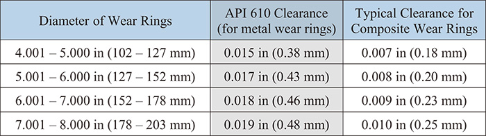 Table 1. Typical clearance values for metal and composite wear rings
One material that has been widely applied is a compression-molded composite of fluoropolymer resin and long carbon fibers oriented in a directional matrix. This directional matrix results in an anisotropic material with different properties in the X-Y plane compared to the Z-axis.
For a typical pump wear component, the X-Y plane is perpendicular to the axis of rotation. The properties for this material are shown in Table 2.
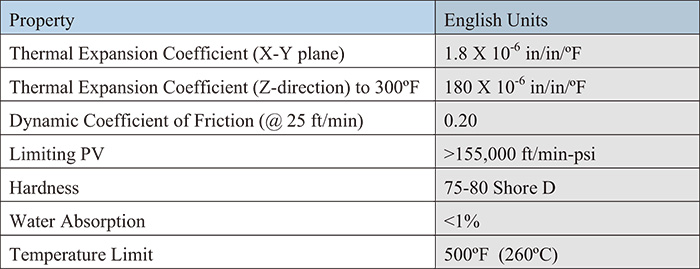 Table 2: Composite material properties (Source: DuPontTM)
The overall combination of properties available in modern composites (see Table 2) set the stage for reliability improvements. The coefficient of thermal expansion, coefficient of friction, and limiting PV (pressure velocity ratio) are all important factors to reduce the risk of material seizure.
More importantly, these properties are essential for the material to survive the normal contact that occurs between rotating and stationary components without wearing out or failing prematurely, particularly during process upsets such as low flow operation, cavitation, or run-dry events.
Because composite materials reduce the risk of seizure or damage during normal contact, running clearance at the wear components can be reduced, typically to 50 percent of the API 610 recommended value for metal wear components. Reduced clearance improves reliability and efficiency, as demonstrated both under controlled conditions and during field studies (Komin, 1990; Pledger 2001).
In a recent study of 61 pumps in an oil refinery, conversion to composite wear materials with reduced clearance reduced the failure rate by 45 percent, and overall vibration levels fell by an average of 25 percent (Aronen, Boulden, Russek, 2007). With this growing history of success, no wonder pump users are turning to composite materials for some of their toughest applications.
The Pump that Couldn't
A large process facility in Central Alberta was having problems with their boiler feed pumps. The original 12 chrome metal wear components caused several pump seizures. Even though the metal components were designed with differential hardness, the original design clearance of 0.016-in (0.406-mm) between rotating and stationary wear components was increased to prevent seizure. The increased clearance led to production problems. When running at full rates, the plant needed to run two pumps in parallel.
Plant reliability and maintenance personnel needed a solution that would allow one pump to meet production needs during full rate operation without increasing the risk of seizure. After consultation with their local repair facility, they decided to overhaul one of their pumps using all composite stationary wear components (case wear rings, inter-stage case bushings, throat bushings, and center-stage bushing) with reduced clearances.
The pump involved is a common design for a process plant boiler feed water pump: 9-stage, horizontally-split, between-bearings design (see Figure 1).
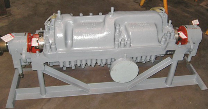 Figure1. The 3-stage boiler feed water pump
This design includes a double-suction first-stage impeller with wear rings, an eye-side wear ring and inter-stage bushing at each of the other eight stages, two throat bushings, and a pressure reducing bushing between the 5th and 9th stages. The impellers are 9.125-in (232-mm) diameter, with 5-in (127-mm) diameter wear rings.
This pump design creates unique challenges which are particularly suited to the application of composite wear components. The rotor configuration - a long, thin shaft (see Figure 2) suspended between bearings - relies heavily upon the wear rings for rotor stability.
While the pump is idle, there is substantial rotor sag (about 0.008-in/0.2-mm) at the center bushing. The rotor sag goes away only when the pump is running and hydrodynamic forces at the wear rings are established. During alignment of the pump to the driver, slow-roll (if coupled to a steam turbine driver), or at start-up, there will be contact at the center stage bushing and other wear components.
During full speed operation off-design conditions like low-flow operation, dry-running, or cavitation can also cause contact between rotating and stationary components, potentially leading to seizure. The service conditions, shown in Table 3, were typical for a process plant boiler feed pump.
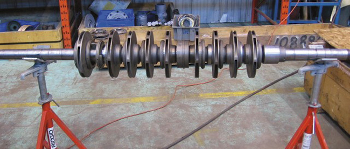 Figure 2. Rotor configuration
Pump Retrofit Details
To optimize the performance of this pump during the available repair time, the repair facility selected a composite material for all of the stationary wear components. The existing 12 percent chrome metal rotating components were used in combination with the composite material. Running clearance between rotating and stationary components was reduced to 0.008-in (0.203-mm), 50 percent of the original design values.
Instead of fabricating new components with complex geometry for the stationary composite components, the existing components were used as holders for composite "inserts." The existing metal bores were increased, and thin-radial-wall composite inserts were manufactured and pressed into the metal holders.
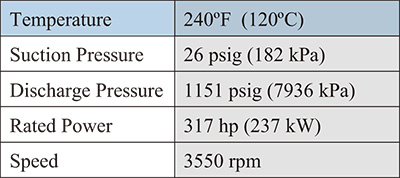 Table 3. Process conditions for boiler feed pump
Additional design detail was needed for the split inter-stage bushings, as shown in Figure 3. Using the existing components as "holders" for the composite reduced the required machining time - eliminating the need for milling slots and other details on the outside diameter of the components.
To prevent axial movement of the composite, the metal holders incorporated a small shoulder on the low pressure side. There were no pins or screws used for anti-rotation purposes; the composite relying upon a heavy interference fit for anti-rotation. With a very low coefficient of friction and other properties that reduce risk of seizure, this method of installation has proven effective with this composite during the past ten years of field experience.
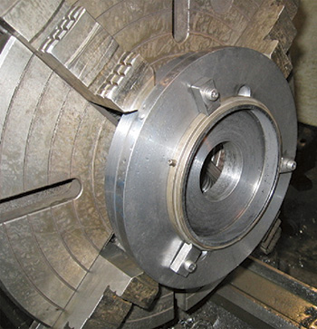 Figure 3. Composite insert in metal case ring holder
Turning the Rotor
Retrofitting a pump with composites is a fairly straightforward proposition. However, as the clearance at the wear components decreases, rotor concentricity becomes more important. To ensure success with the new, tighter clearance, the repair facility must pay attention to a few fundamental details.
Before the rotor is installed, the pump should be fully inspected. The split-line should be checked to ensure it is true, the line bore and seal chamber bore should be checked for concentricity (see Figure 4), and the rotating element should have limited run-out (typically 0.002-in max).
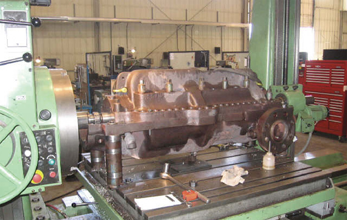 Figure 4, below. Line boring the pump case
Individual components should be checked for condition and concentricity. For example, if using the existing case ring as a holder for a composite insert, the metal ring should fit properly within the pump case. Loose or distorted components should be repaired or replaced as needed.
Once the rotor is in place, the case bolted together, and the bearing housings doweled and bolted in place, one final check is needed. The rotor should turn freely, which requires a reasonable understanding of the pump internals.
Due to the aforementioned rotor sag (along with friction from the mechanical seal faces and bearings), there will be contact between rotating and stationary components. However, the resistance should not be excessive, which would indicate mechanical interference between rotating and stationary parts. Once the rotor is turning, a competent repair facility will be capable of determining whether the rotor is turning freely or is inhibited by mechanical interference, which could cause premature failure of the pump.
Results of Retrofit
The boiler feed water pump in Alberta has been running since June 2007 and the retrofit has delivered everything plant personnel wanted:
- One pump now meets full load production demands.
- Risk of metal to metal seizure is dramatically reduced.
- The pump is running with very low vibration compared to previous levels.
As an added bonus, amperage draw on the motor has fallen by 5 percent. Using the rated power of 317-hp (237-kW) and assuming a power cost of $0.06/kWh (a typical price in North America), this is worth a lot of money: For this one pump, the plant will save roughly $6,200 for every year of operation.
Conclusions
The benefits of running a pump with reduced clearance at the wear rings and similar components are well documented by field studies and pump design texts. Composite materials allow pump repair facilities to reduce the clearance at the wear components to values substantially less than the recommended minimums for metal components as listed in API 610.
Furthermore, the latest generation composites have material properties which can stand up to tough services, process upsets, and off-design operation, reducing the risk of pump failure.
Quality pump overhaul practices help deliver the full benefit of composite materials with reduced clearance. Thorough component inspection, verification of rotor concentricity within the case, and proper composite installation methods contributed to the success of this application.
References
- Aronen, R., Boulden, B., and Russek, M., 2007, "Driving Pump Reliability Forward with Advanced Composite Wear Rings," Proceedings of the 23rd International Pump Users Symposium, Turbomachinery Laboratory, Texas A&M University, College Station, Texas, pp. 15-19.
- Bloch, H. P., 1988, Practical Machinery Management for Process Plants Volume 1: Improving Machinery Reliability, Second Edition, Houston, Texas: Gulf Publishing Company.
- Bloch, H. P. and Geitner, F. K., 1985, Practical Machinery Management for Process Plants, Volume 4: Major Process Equipment Maintenance and Repair, Houston, Texas, Gulf Publishing Company.
- Komin, R. P., 1990, "Improving Pump Reliability in Light Hydrocarbon and Condensate Service With Metal Filled Graphite Wear Parts," Proceedings of the Seventh International Pump Users Symposium, Turbomachinery Laboratory, Texas A&M University, College Station, Texas, pp. 49-54.
- Lobanoff, V. S. and Ross, R. R., 1992, Centrifugal Pumps: Design and Application, Second Edition, Houston, Texas: Gulf Publishing Company.
- Pledger, J. P., 2001, "Improving Pump Performance & Efficiency with Composite Wear Components," World Pumps, Number 420.
Pumps & Systems, November 2007