


Pumps & Systems, November 2007
Propane refrigeration systems are often required in the natural gas processing industry to provide the required chilling in condensing heavy components for a rich gas. This study explains a simple correlation to estimate compressor power and condenser duty per refrigeration duty in three-stage propane refrigerant systems - important parameters to consider when designing any refrigeration system.
Refrigeration systems are very common in the natural gas processing industry for NGL recovery and hydrocarbon dew point control. Selection of a refrigerant is generally based upon temperature requirements, availability, economics, and previous experience. Propane is one of the best refrigerants since it does not require significant technical changes in the existing refrigeration systems.
In this process, the natural gas stream is chilled with an external propane refrigeration system, and then the condensed liquids are separated in a low temperature separator and stabilized in a column. Propane is not corrosive with many materials like aluminum, brass, bronze, copper, stainless steel, silver, etc. Thus it is fully compatible with existing components such as heat exchangers, expansion valves, compressors, lubricants and copper tubing, which are currently used in refrigeration systems.
The propane refrigeration system is designed to provide the required chilling in gas-processing applications. Refrigeration systems utilizing one, two, three, or four stages of compression have been successfully operated in various services. However, the number of levels of refrigeration generally depends upon the number of compression stages required, interstage heat loads, economics, and the type of compression.
A two-stage refrigeration system and interstage flash economizer can result in significant savings. Additional savings can be realized by removing process heat at the interstage level rather than at the low stage level. Additional power savings can be achieved by using a three-stage compression system. As with a two-stage system, flash economization and/or an intermediate heat load can be used. The savings, while not as dramatic as the two-stage versus one-stage, can still be significant enough to justify the additional equipment (GPSA, 1998). A typical three-stage propane refrigeration system is shown in Figure 1.
 Figure 1. Schematic flow diagram of three-stage propane refrigeration system.
Energy consumption is frequently reduced as the number of stages increases. However, for a propane refrigeration system, the installation cost of such refrigeration systems increases as the number of stages increases.
Determination of refrigeration level is based upon minimum temperature required in process, considering the temperature approach for heat transfer equipments where condensing temperature has a significant effect on the compression power and condensing duty requirements. Considering this, an essential need exists for appropriately determining these design parameters that affect the optimization of a propane refrigeration system.
New Proposed Correlation
Equation 1 presents a new correlation in which four coefficients are used to correlate compressor power and the condenser duty per refrigeration duty in a three-stage propane refrigerant system:
 In the above equations, Q is the compressor power (MW) or condenser duty per refrigeration duty (kW) in a three-stage propane refrigerant cycle, and Tevp and Tcon are the temperatures of evaporator and refrigerator condenser in deg K, respectively. The tuned coefficients used in Equations 2 to 5 are given in Table 1 for compressor power and condenser duty determination. These tuned coefficients are changed if more accurate experimental data are available.
 Table 1. Tuned coefficients used in Equations 2 to 5
In order to apply this correlation to most of the commercially available compressors, a polytropic efficiency of 0.77 is assumed. The polytropic efficiency is converted into an isentropic efficiency to include the effects of compression ratio and specific heat ratio for propane refrigerant. For well balanced and efficient operation of the compressor, an equal compression ratio between stages is employed.
The pressures at the compressor suction and side load inlet nozzles were adjusted by 10-kPa to allow for pressure drop. These data also include 70-kPa pressure-drop across the refrigerant condenser for propane.
Results
Figures 2 and 3 illustrate the obtained results of the new developed correlation compared with some data reported by Mehra (1997). A good agreement between the predicted and reported values is evident. It is therefore recommended to use this simple-to-use correlation for predicting the compressor power and condenser duty per refrigeration duty in the three-stage propane refrigerant system within the proposed ranges.
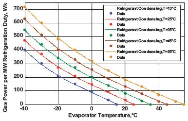 Figure 2. Comparing predicted values of the new developed correlation for predicting compressor power per MW refrigeration duty with some data reported by Mehra (1997).
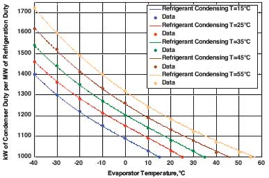 Figure 3. Comparing predicted values of the new developed correlation for predicting condenser duty per MW of refrigerant duty with some data reported by Mehra (1997).
The new correlation is suitable for the range of evaporator temperatures between negative 40-deg C and 60-deg C and the refrigerant condensing temperatures range between 10-deg C to 70-deg C.
References
GPSA Engineering Data Book, 11th Edition, Gas Processors Suppliers Association (GPSA), Tulsa, OK, USA (1998).
Mehra, Y.R., "Refrigerant Properties of Ethylene, Ethane, Propylene and Propane", Chem. Eng. 131, 95, 165 (1997).