Overall vibration trending is excellent for monitoring rotating machinery health, but not generally effective for tracking reciprocating compressors. A new generation of Reciprocating Machinery Protector technology is very sensitive to compressor faults in their early development stages, yet less likely to give false trips. Here's how it works.
Many typical faults on reciprocating machinery are characterized by mechanical looseness, which results in impacting or shock events in the machine.
Impacts produce very short duration pulses in the vibration signal that generally have little effect on the overall vibration level. Thus, conventional trending techniques do not detect these types of faults at an early stage. This creates a significant problem, because critical damage or even catastrophic failure can occur in a very short period of time after the onset of these typical faults:
- Loose or broken bolts
- Loose or cracked rod nuts
- Cracked connecting or piston rod
- Excessive crosshead/slipper clearance
- Excessive clearance in connecting pins
- Liquid or debris in the cylinder
- Scoring in the cylinder
- Other cracked or broken parts
Impact transmitters have been successfully used to monitor compressor faults for many years. However, their effectiveness is quite sensitive to the shock threshold level selected, since they only monitor shock pulses which exceed a single threshold level. If the level is incorrectly selected (too high or too low), it results in either false trips or insufficient warning and machine damage.
What is RMP?
Reciprocating Machinery Protector (RMP) technology introduces a new generation impact transmitter that is very sensitive to compressor faults in their early stages of development, yet less likely to give false trips than conventional transmitters. It improves on existing technology in the following ways:
- Peak amplitude of routine data which does not exceed a shock threshold level is measured and can be trended.
- Peaks are evaluated relative to two shock threshold.
- Levels, rather than one. This allows more flexibility in setting thresholds, resulting in earlier warning of faults without false trips.
- Peak counts (i.e., peaks which exceed thresholds) are weighted based on their levels to help better quantify vibration severity.
- A "dead time" is used to eliminate false peak counts due to mechanical ringing of lightly damped structures caused by the impacts.
- Monitoring parameters are programmable, so the process may be optimized for particular machines.
- The monitor has a higher frequency response than existing units.
Impact Data
Figures 1 and 2 show vibration data taken on a good and bad compressor, respectively. Even though there are significant differences in peak amplitudes due to the impacts, the overall vibration level does not change enough to reliably detect it.
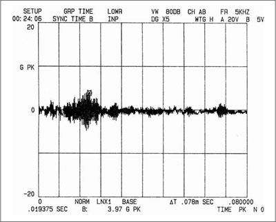 Figure 1. Time waveform data from a good compressor.
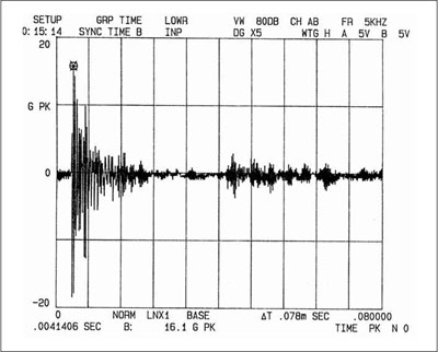 Figure 2. Time waveform data from a bad compressor
RMP technology uses special high speed peak detection circuitry to accurately measure the amplitude of each shock event occurring within a preset sample time (typically 12 to 16 cycles of operation) and compares them with two preset shock threshold levels.
Based on improved exceedance criteria developed from empirical data, a Reciprocating Fault Index (RFI) is calculated to indicate machinery health. This index provides a better indication than that provided by conventional impact transmitters.
Overall Trend vs. RFI Trend Plots
The difference between monitoring overall vibration level and RFI on a reciprocating compressor is shown in Figure 3. This is a trend plot over a 60-min period that shows both measurements on the same compressor.
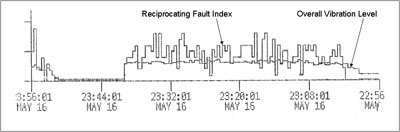 Figure 3. Trend graph of an overall vibration level and RFI. Note that time runs right to left.
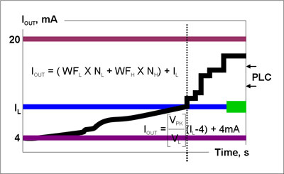
The RMP device continuously monitors embedded acceleration signal using a high-speed peak detector. Using an internal microprocessor, it compares each peak detected against low and high shock threshold levels, calculates RFI, and outputs a 4-mA to 20-mA signal proportional to the RFI. Figure 8 shows a typical trend plot of RFI.
If no peaks exceed either threshold, RFI is simply equal to the peak amplitude detected. Thus, if a data logger is used with the system, trending can be implemented. If any peak in the sample time exceeds either threshold, the processor counts them, applies a weighting factor based on amplitude, and computes RFI. The output of the RMP is typically routed to a meter, PLC, or other device capable of tripping warning and critical alarms based on output. Default values for these alarms are provided with the unit.
The RMP Device
RMP technology uses a two-wire device that operates off of standard 24-V loop power and has a 4-mA to 20-mA output signal proportional to the RFI. Its output can be connected to a PLC, DCS, or SCADA system, as well as many other standard instruments accepting a 4-mA to 20-mA signal.
The system used should have either dual relays or display functions and be set to provide notification when the RFI exceeds either the warning or critical alarm level. It may also be set to shut the machine down when the critical alarm level is reached.
Monitoring parameters can be factory set, based only on the RPM device of the compressor and default settings. All RMP device parameters are user adjustable through an optional USB programmer and supplied software.
Mounting an RMP Device
Shock and vibration data are measured using an industrial accelerometer operating over a wide frequency range, thereby responding accurately to impact events. An RMP device contains an integral accelerometer (for ease of installation) housed inside a compact, hermetically sealed, industrial accelerometer-type body.
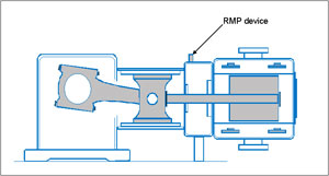
This robust unit is typically mounted to the crosshead or crosshead slipper using a single ¼-28 mounting stud with sensing axis perpendicular to the piston rod motion, as noted in Figure 7. If the compressor does not have a crosshead, it is mounted to crankshaft side of the cylinder.
 The RMP device continuously monitors embedded acceleration signal using a high-speed peak detector. Using an internal microprocessor, it compares each peak detected against low and high shock threshold levels, calculates RFI, and outputs a 4-mA to 20-mA signal proportional to the RFI. Figure 8 shows a typical trend plot of RFI.
 If no peaks exceed either threshold, RFI is simply equal to the peak amplitude detected. Thus, if a data logger is used with the system, trending can be implemented. If any peak in the sample time exceeds either threshold, the processor counts them, applies a weighting factor based on amplitude, and computes RFI. The output of the RMP is typically routed to a meter, PLC, or other device capable of tripping warning and critical alarms based on output. Default values for these alarms are provided with the unit.
Case History
A rebuilt six cylinder compressor was placed into service as part of an expansion project in a gas plant. This compressor is driven with a 3000-hp electric motor and runs at 300-rpm. The plant routinely monitors and trends velocity vibration measurements on most of their equipment, including reciprocating compressors. They decided to install an impact monitor on each compressor cylinder on this machine.
At startup, the transmitter alarm relay tripped and took the compressor offline. While attempting to restart the machine, the impact transmitter again tripped and took them offline. An investigation discovered that the retaining bolts on the high-pressure packing case had not been properly tightened. Had this error not been caught, the looseness would have gotten worse and would have likely led to catastrophic failure.
Pumps & Systems, September 2007