
One of the critical parameters in compressor design and selection is the compression ratio, often denoted as r. The compression ratio is simply the ratio of the absolute stage discharge pressure to the absolute stage suction pressure.
Because most gases increase in temperature when they are compressed, the final compressor outlet temperature is always a concern. A high discharge temperature can lead to the failure of internal components due to material degradation or excessive thermal expansion. Compression ratio is also important in determining required horsepower; the higher the ratio, the greater the required horsepower for that stage.
Compression Ratio versus Discharge Temperature
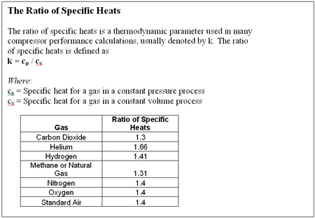
Here is a simple example of how to calculate compression ratio. For example, we will compress a gas with a ratio of specific heats of 1.3 (see ratio of specific heats box) from a suction pressure -0.5 psig to a discharge pressure of 35 psig. To calculate the compression ratio, first convert both of these pressures to absolute pressure by adding 14.7 to each term and then dividing the absolute discharge pressure by the absolute suction pressure:
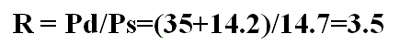
Equation 1
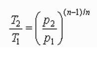
Once we know the compression ratio (and assuming there are no internal losses), we can determine the theoretical discharge temperature using Equation 2, which is based on adiabatic compression.
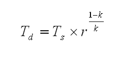
Equation 2
Where:
T = deg R
k = Ratio of specific heat
r = Compression ratio calculated by Equation 1.
Assuming a suction temperature of 60 deg F, we arrive at a theoretical discharge temperature (Td) of 234 deg F.
We will take this exercise a step further by increasing the compressor discharge pressure in 5 psi increments to see what happens to the discharge temperature. Table 1 summarizes the results. As the discharge pressure increases, the compression ratio rises and the discharge temperature (Td) correspondingly increases. In this example, Td increases from 234.3 deg F for a compression ratio of 3.5 to 335.7 deg F for a compression ratio of 6.32.
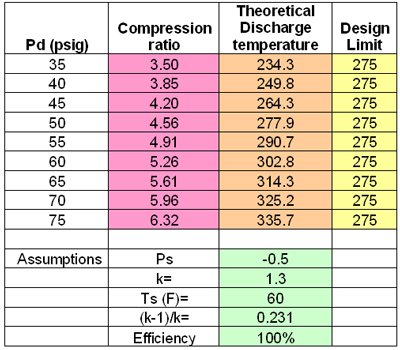
Table 1. The Effect of Discharge Pressure on the Theoretical Discharge Temperature
Design Temperature Margin
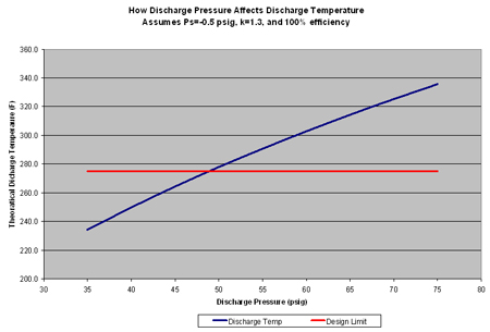
Compared to a hypothetical design limit of 275 deg F, we begin to exceed our design limit temperature at a compressor discharge pressure of 50 psig. The relationship between the theoretical discharge temperature and design limit temperature can be seen in Figure 1. It is a good idea to select a conservative design temperature limit during the selection phase of a project to ensure a safe operating margin to take unknown or unexpected internal cylinder losses into account.
For example, a potential compressor has a recommended discharge temperature alarm limit of 325 deg F and an automatic shutdown at 350 deg F. If the actual discharge pressure is 60 psig, expect a minimum Td of about 303 deg F. (Remember that the discharge temperature values in Table 1 are theoretical values.) In reality, it will be higher due to internal losses as the compressor experiences normal degradation. If the actual Td is more like 318 deg F, the margin will only be 7 deg F, which is going to lead to countless alarms and midnight phone calls.
To avoid this situation, use a conservative design discharge temperature specification and use more compression stages to ensure smaller compression ratios per stage. Table 1 shows that for this example, design compression ratios should not exceed 4.5 per stage to maintain a healthy margin between the operating temperature and alarm limit.
Cautionary Note: These examples are based on theoretical adiabatic compression calculations. Adiabatic compression formulas are used to approximate the performance of reciprocating compressors. Readers should work with compressor manufacturers to determine actual compression ratio and discharge temperature limits for specific compressor designs. The theoretical calculations used in this column were used to demonstrate the general trend expected from high and higher compression ratios.
For centrifugal compressors, the following theoretical temperature rise equation, based on polytropic compression, is commonly used:
Equation 3
Here (n-1)/n is defined by the relationship:
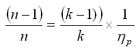 , where p is the compressor's polytropic efficiency
Equation 3 should only be used to estimate the theoretical discharge temperature in dynamic compressors.
Design Tradeoffs
There is always a trade-off between the number of compression stages and the compressor discharge temperature at each stage. The more stages, the costlier the compressor will be due to complexity and the more cooling required at each stage. However, the more compression stages installed, the smaller the temperature rise will be across each stage, allowing the compressor components to operate cooler and more reliably. This is the trade-off all compressor professionals must make as they begin their selection process.
The overall compression ratio is the product of all the individual compression ratios, i.e., ro=r1 x r2 x r3 x etc. Assuming all stages have the same compression ratio, we can write:
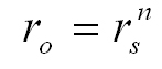
Equation 4
Where:
n = The number of stages
rs = The compression ratio per stage.
From this relationship, we can conclude that the number of stages required to achieve the required overall ratio is:
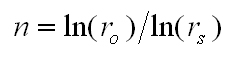
Equation 5
For example, if the required ro is 20 and the recommended maximum rs is 4.5, then:
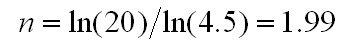
Equation 6
or two stages of compression. In general, we can conclude that the smaller the allowable compression ratio (rs), the more stages (n) are required.
My recommendation is try to use the widest economical margin between the calculated discharge temperature and the compressor design temperature limit. In the example above, I recommended a design margin of 50 deg F (325 deg F - 275 deg F) to provide a buffer for unforeseen internal compressor degradation. If factors like dirty gas are expected, increase the design margin even further.
Remember, the compressor manufacturer will help users select the right compressor for their applications. Compressor manufacturers need to know the most accurate compression ratio, gas composition and suction temperature specification available to help select an efficient and trouble free compressor.
Click here to see a Readers Response to this article.
