
Q. When operating centrifugal pumps on corrosive or erosive applications, how can the user determine when the casing wall is worn too thin for safe operation? What is the minimum safe operating wall thickness?A. Pump components are designed with a corrosion allowance that varies by component. Casings and rear cover plates may have up to 3-mm (0.13-in) allowance while components such as sleeves may be as low as 0.24-mm (0.01-in). The pump manufacturer should be consulted for specific corrosion allowances. When 70 percent of the corrosion allowance is gone, the pump should be shut down for service or replacement.
Most forms of corrosion can be detected by visual inspection, the easiest and most economical method of monitoring corrosion. However, stress corrosion cracking usually occurs without any visible signs, which can result in a sudden and sometimes catastrophic failure. Visual inspection of pump internals can reveal the degree of general corrosion as well as signs of localized corrosion like pitting and crevice corrosion. Particular attention should be paid to complete inspection of fasteners as corrosion often takes place in areas hidden from view. Pressure boundary leakage may expose normally non-wetted fasteners to corrosive pumpage.
Visual inspection can be supplemented with dimensional checks of key components, which can then be used to calculate the amount of general corrosion that the pump is experiencing.
Non-visual methods of inspection can also be used. These include electrical resistance (ER), linear polarization resistance (LPR) and ultrasonic thickness measurement (UTM).
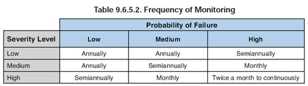
Frequency of monitoring depends on the severity level of the consequences and the probability of failure. Actual experience may be used to determine whether more or less frequent monitoring is appropriate for specific services.
See Table 9.6.5.2. below.
 Q. What is the best way to avoid excessive pipe strains on a pump caused by expansion in piping due to temperature change? Are expansion joints a viable solution?
A. Expansion joints are not the best solution to excessive pipe strains. Typical expansion joints do not restrain the axial forces in the piping due to the liquid pressure. For example, the axial force caused by 150-psi internal pressure in a 6-in pipe is 4,241-lbs. This force is usually restrained by the pipe, but with an expansion joint, the pipe does not do this. Such forces must be carried by the pump if the expansion joint is close to the pump. The maximum allowable force on the discharge flange of an 8x6x13 ASME B73.1 pump is 3,500-lbs, according to ANSI/HI 9.6.3 Centrifugal and Vertical Pumps for Allowable Nozzle Loads.
At 150-psi internal pressure, the axial force exceeds the allowable limit. This internal pressure force can be restrained with external tie rods on the expansion joint. However, tie rods limit the expansion joint's flexibility to forces perpendicular to the pipe, which may not be acceptable and must be evaluated.
A pipe anchor close to the pump is normally a better solution. The piping configuration can also have bends or turns designed to accommodate the pipe's thermal expansion.
Another approach to this problem is a free floating pump or a spring-mounted baseplate. Close-coupled pump designs can facilitate this approach. Vertical in-line pumps are a variation of the close-coupled design and are available for many process applications. VIL pumps can transmit substantial forces through the casing between the discharge and suction pipe. ANSI/HI 9.6.3 shows the allowable force between discharge and suction flange of a 4-in discharge pump is 18,704-lbs.
Spring-mounted baseplates can also work well, but the baseplate must have sufficient stiffness to maintain coupling alignment without relying on a concrete foundation.
Q. In applications where NPSH available is low, it is often necessary to apply an oversized centrifugal pump that operates at 50 percent of its design flow rate to obtain a pump with low NPSH required values. What is the downside of doing this?
A. At 50 percent of BEP, most pumps begin operating in a mode including suction recirculation, which results in vortices. The vortices cause an increase in cavitation and damage to the impeller. Some manufacturers recognize this phenomenon and show an increase in NPSHR on the pump curve.
In addition to suction recirculation, the abnormal flow distribution through the pump causes an increase in the radial hydraulic forces on the impeller. This increase in radial forces causes higher loads on bearings and greater deflection of the shaft at the mechanical seal, which can result in premature pump failure and a reduced Mean Time Between Repairs (MTBR).
Pump efficiency at 50 percent of BEP is lower, resulting in substantial increases in power consumption compared to an appropriately sized pump. The motor selection will also be affected by the higher horsepower requirements of the oversized pump.
Specifying a pump that operates at lower speed will often avoid these problems. Any increase in initial cost should be quickly offset by the power savings.
Pumps & Systems, September 2008
