
Wet Environments
Water chemical compatibility and electrical interference are two major challenges for control systems. Two major sources of fresh water can limit the performance of the control system.
Ground Water
Ground water, found from few feet to several hundreds of feet below the Earth's surface, is a major source of fresh water and is found all over Earth. This water source may contain dissolved minerals and gases such as calcium, magnesium, sulfates (magnesium sulfate, calcium sulfate or sodium sulfate), iron, chlorides and hydrogen sulfide.
If not treated at the source, these dissolved solids can cause pipes, valves, pumps and electronic pressure measuring devices to corrode, leading to system failure. The corrosion of pipes and pumps may occur as the pH level of the water drops below seven and will accelerate if the temperature rises above 15 deg C. Figure 1 shows a pressure sensing device that failed due to pitting, a major corrosion mechanism.
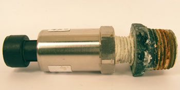
Figure 1. Corrosion of pressure transducer due to pitting in water
Desalination
A desalination system can produce fresh water from seawater and challenging brackish sources using either distillation or reverse osmosis processes. The distillation process is a physical separation process between the salt and water and not a chemical reaction.
In the reverse osmosis process, pressure pumps are used to force saline water through a membrane, retaining the solute on the upstream side while allowing pure water to pass to the downstream side. Brackish water containing salts less than 5,000 ppm can be economically treated in comparison to sea water.
In the desalination process, care must be observed for pumps, pipes and electronic pressure sensing devices for salt levels, operating temperature and cavitation. Figure 2 shows a 2,000 psi pressure sensor constructed from 316L wetted parts with pin holes due to severe pitting while operating off the coast of Australia. Sea water salt content and temperature were observed to be 34,000 ppm and 28 deg C, respectively.
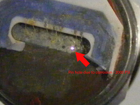
Figure 2. Pin holes can be seen with back light through a 1.12 mm (0.044 in) thick 316L diaphragm
Pressure Sensing in Wet Environments
Since pressure sensing diaphragms are the thinnest section of the pressure sensing device, and mainly made from metals, it is important to select the correct metal for long, reliable operation. Avoid low cost sensors that may require excessive maintenance and downtime. Table 1 shows some of the commonly used metals for sensor diaphragms and their uses in different water types.
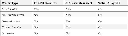
Table 1. Wet media compatibility with some of the common metals used in sensor diaphragms
Noisy Environments
Electrical noise generated in an electronic drive pumping system is a serious problem and can be easily overlooked.
Electrical noise can be controlled and managed in skid-based systems, which are located inside a building with good grounding. An outdoor system with poor grounding, such as residential or commercial submersible or marine-based pumps, is a different story. These systems are typically driven by a variable frequency drive (VFD), which consists of forced air, a computer controlled panel, electric motor and electronic pressure sensing device such as a sensor, transducer or transmitter. Depending on the well depth or water source, connecting these components may require tens to hundreds of feet of cable. In most cases, the cable is not shielded to save money and weight. The majority of installers do not pay attention to the quality of the grounding, leading to stray voltages and ground loop currents that play havoc with system reliability.
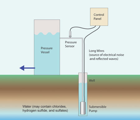
Figure 3 shows a typical VFD-based submersible pumping system for a domestic/commercial application.
The VFD offers the advantage of a closed loop system, but it can produce unexpected electrical results. The VFD converts the incoming 50 or 60 Hz AC power to a DC voltage and chops this DC voltage with power semiconductor devices at high frequencies to mimic AC of variable amplitude and frequency to vary the speed of the electric motor. This process generates large amounts of electrical pollution in the form of radiated (~ 300 V/m) and conducted emissions that will disrupt the operation of the controller and pressure sensor electronics.
Another result is sometimes referred to as reflected waves, which can be as high as twice the output of the VFD applied to the motor. This is a result of the impedance mismatch of the long motor leads and motor windings. Not only will it destroy the insulation of the motor and bearings leading to motor failure, it will also cause stray voltages to travel in the water pipes, leading to electrical shock. These stray voltages can cause insulation breakdown of the pressure sensing devices, leading to complete system failure. Depending on the output of the pressure sensing device, the motor may not run at all or at full speed, causing unwanted pressure buildup in the system.
Pressure Sensing in Noisy Environments
Correct electronic pressure sensing topology must be selected in this noisy environment. Pressure sensors are low level output devices, between 2 mV/V to 10 mV/V with four wires. These devices provide ratiometric output with respect to applied DC voltage. Under noisy conditions, the cable length must be limited to within 10 ft with the shield. Additional Radio Frequency Interference (RFI) filtering may be needed to make this device interface successfully with electronics.
Pressure transducers provide high level output signals such as 1-5VDC or 1-6VDC that allow cable lengths to be extended to approximately 15 feet. Beyond this length in a noisy environment, the output of the transducer can oscillate and cause stability problems for the controller if the output of the transducer and the input of the controller are terminated correctly against the transmission line effects of the cable.
Pressure transmitters in the form of 4-20mA, two wire loop-powered output signal are ideal for long cable lengths. The two wire transmitter is also inherently immune to noise in comparison to the pressure sensor and transducer. Correct filtering should be applied within the transmitter against noise on the supply voltage associated with long cables and switching power supplies.
Additional Notes on Pressure Sensing
For all the above pressure sensing devices, additional protection and considerations must also be applied against reflected waves when considering electronic pressure sensing devices. This will allow long, safe operation in wet and noisy environments. Some of these features, not a complete list, include:
a) Passive and semiconductor energy-absorbing devices and ferrites (optional) must be used between input and output lines and casing to ensure sufficient protection against stray voltages, corona discharge and high static voltages. Special consideration must be paid to the operating voltage and power dissipation of these devices.
b) Use pressure sensing devices with high dielectric strength such as 400VAC (minimum) between case and all input/output wires. This will allow the sensor to survive reflected waves and stray voltages in conjunction with (a).
c) Use shielded cables where possible. Depending on the application and surroundings of the pumping system, the shield may be grounded at the pressure sensing side, the opposite side or both ends.
Pumps & Systems, January 2010
