
A direct-coupled steam turbine and generator in a main plant power had developed high vibration. The unit had been running for 8 years without any visible or recordable vibration problems. However, the turbine non-drive end (NDE) proximity probes had begun to register vibration and would trip the unit after 45 percent of the full load was exceeded.
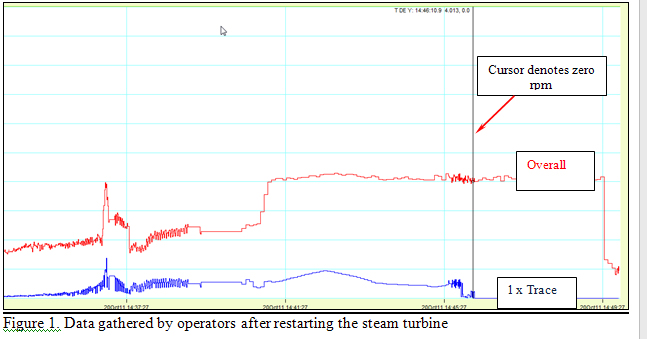
After correcting the minor proximity probe cabling deficiencies, which was the assumed problem, the unit was started and operators collected a set of data. The overall trend indicated an increase in vibration dependent on the main steam valve opening. The unit would exhibit two vibration increases which were strictly related to the two load conditions. First, the vibration increase would calm down to previous and acceptable levels. Second, the increase would spike and trip the unit.
Restart Data
With the speed constant at 6,015 rpm, a ghost peak—a peak of unknown origin—would speed up as shown in Figure 1, from F1 to F2, before the overall vibration amplitude increased and eventually tripped the unit. Although the unit tripped, as seen by the blue “1 x trace,” the ghost peak was still apparent and contributing to the overall vibration level.
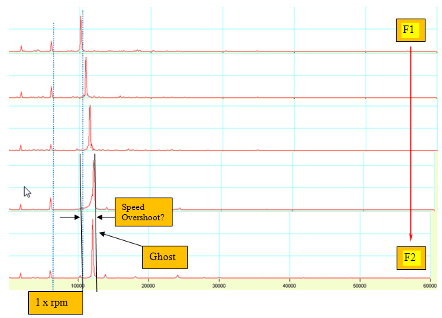
According to the data, something was speeding up, slowing down and continuing to run. Also, the ghost peak was still exciting a resonance. What was causing the vibration and ghost peak?
Solo Turbine Test
As a next step, the unit was decoupled and the turbine was tested on its own with the same results. At this point, the operators could conclude that the ghost peak was isolated to the turbine. Based on the solo run, a simplified finite element analysis (FEA) rotor model was made to determine the natural modes (see Figure 2).
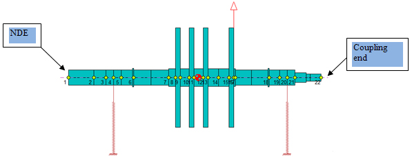
Figure 2. Rotor model with sleeve bearings and no foundation effects
FEA Results
Two calculated modes of interest were found based on the FEA rotor model (see Figure 3). These modes of interest illustrate the turbine NDE whipping mode at 5,982 rpm and the system “S” mode at 10,961 rpm. This result was interesting. The first calculated mode is about half the recorded F2, ghost peak frequency but coincides with the turbine running speed. At the same time, the “S” calculated mode matches the ghost peak frequency of 10,961 rpm.
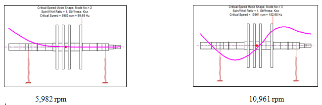
Figure 3. Modes on interest resulting from the FEA model
The turbine NDE whipping mode corresponds to the recorded 1x peak of the first page stacked fast Fourier transform (FFT) plots, while the "S" mode matches well with the region where the ghost peak frequency occurred. The next step was to determine at which bearing the rotor was more sensitive.
The drive-end (DE) bearing amplification factor (AF) at the running speed of 6,000 rpm was definitely visible and confirmed that it would affect the calculated “S” mode. The NDE bearing AF at 6,000 rpm produced a negligible effect.
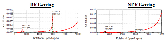
Figure 4. Bearing amplification factors
The turning rotor produced a force causing the DE shaft to respond, which caused an unknown condition to excite the shaft “S” mode. The test operators did, however, know that the ghost peak frequency would present itself with additional loading demand—such as when the turbine’s steam valves opened.
Action Taken
Since the problem narrowed down to the turbine, the operators agreed to check the steam valve mechanism and take the additional step of opening the turbine case for inspection. Upon examining the turbine, the operators discovered that the last turbine wheel had broken away from its key-way to the shaft (see Figure 5). This was the closest wheel to the coupling (DE) side.
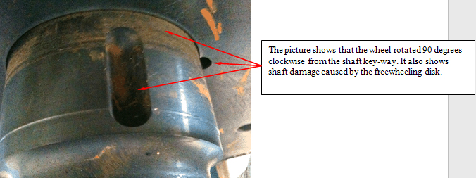
Figure 5. Rotor model with sleeve bearings and no foundation effects
Conclusion
The turbine wheel, with its out of balance location, was exciting the rotational speed (FFT – 1x) manifesting as unbalance. With the load demand as well as the blast of additional steam, the non-keyed wheel would speed up and coincide with the shaft’s first bending or “S” mode. Even with the best instrumentation and years of experience, it was not possible to come to only one conclusion without physically opening the turbine case and identifying the part causing the ghost peak frequency.
