
Pump monitoring instrumentation is often not included with installations, but proper sensors can protect a pump and help with efficient operation.
Pumps of all sizes are used throughout the process industries to transfer a wide range of fluids. Along with proper pump selection and installation to address a particular application, determining what kind of information is needed to protect the pump and help it operate more efficiently is important.
The Hydraulic Institute publication Optimizing Pumping Systems Executive Summary, states that a pump system with no means of measuring the flow, pressure or power is an inefficient pumping system. Unfortunately, instrumentation to provide information for pump protection or performance monitoring is often not specified or supplied at the time of installation. Fortunately, a modest investment in sensors can help improve the reliability and performance of expensive pumps and pump systems. In some cases, spending a few hundred or a few thousand dollars on instrumentation can protect a $50,000 pump from serious damage or help prevent even greater operation losses.
Pump Protection
Pump protection starts by providing the proper sensors for monitoring key pump functions. If the necessary monitoring devices or provision for their installation were not included in the original pump installation, they need to be added. This does not have to be an extensive addition or upgrade.
Centrifugal pumps have a specified performance window of operating curves. Moving out of that window or moving too much within it may produce stresses that can result in damage to the pump. Installing the proper sensors, especially on more costly (in terms of the pump itself, energy usage and maintenance history) pumps, can help identify problems before they become too serious, damage the pump and impact maintenance and operation resources.
For example, installing a pressure sensor on the suction side to measure net positive suction head available (NPSHa) will help show if a pump is not running within the proper pump performance curves. Temperature or pump vibration monitoring sensors can indicate mechanical problems before they become advanced. Specifying an empty pipe detection (EPD) or low/no flow sensor can indicate when pumps have trouble.
A pump protection system that does not require running new wiring uses a self-powered WirelessHART adaptor combined with low-cost HART pressure, temperature transmitter/sensors and flow meters (see Figure 1) to help provide pump condition information. The protection system will deliver pump suction pressure, discharge pressure and temperature information to a recorder, data server or web portal on a temporary or permanent basis. The pressure differential across the pump is determined by the difference between the measured suction and discharge pressures.
To avoid cavitation conditions, the NPSHa must be greater than or equal to the net positive suction head required (NPSHr). Monitoring the suction head (pressure in terms of water column) for this condition can help identify problems that can damage the pump. A number of factors can change the NPSHr—including but not limited to increases in flow rate or changes to the head (such as pressure from fluid density or level) in a supply tank in front of the pump.
High pressure or vacuum conditions may impact some applications. Ceramic pressure sensors that can measure abrupt vacuum or pressure changes without being damaged themselves can be used in these situations. Ceramic sensor pressure transmitters can also resist a great deal of direct physical diaphragm abuse without affecting calibration even when repeatedly relocated to different pump installations.
.jpg)
Figure 1. Sensors can be installed to monitor pump performance by measuring suction and discharge pressure, temperature, seal-pot level and other variables.
A pump is “dead-headed” when it operates with no flow. If no fluid is entering the impeller of the pump, it will churn the same volume of fluid as it rotates. Friction will lead to increased fluid temperature which can reach the point at which the fluid flashes into vapor, disrupting cooling flow to the pump’s bearings and packing. If this condition continues, it can cause excessive pump wear and damage.
A flow switch installed at the pump inlet can alarm when the flow rate into the pump drops below a preset rate while the pump is running. For less than $400, a calorimetric flow switch can indicate a low/no flow condition with which damage can occur.
A pump is “dry running,” or in an empty pipe condition, when fluid is not sufficiently delivered to the suction side of the pump. One way to detect this condition is to specify an EPD switch. If a pump is allowed to run dry, it can cost thousands to recondition or repair. At $400, an EPD switch is cost-effective pump life insurance. Electronic tuning fork EPD switches are more reliable than float sensor EPDs in some pumping applications.
For example, an OEM skid builder had problems with floats sticking because material in the fluid coated the floats. In this application, the pump could not run dry and had to shut off when no water was available for the shaft packing. The skid builder installed tuning fork EPD switches instead of floats, and false trips went to zero. No pump failures were reported because of switch malfunction, and no burnt pump packing was reported.
EPDs are also available within some flow meters. Most pump systems can benefit from monitoring via a flow meter, so it makes sense to spec one with EPD at the beginning.
If a flow meter, flow switch or an EPD switch is not installed, a temperature sensor can sometimes be used to sense some problems that can occur from low or no flow. The temperature sensor has to react quickly before damage can occur. One pump temperature sensor uses thin-film technology to react seven times faster than standard temperature sensors. It also has a stainless steel housing, making it suitable for pump applications in food, chemical and pharmaceutical industries.
Seal Pot Levels
Pumping systems involving toxic, hazardous or corrosive fluids cannot allow leaks into the environment. In such cases, a pump may have a double or tandem seal that uses a compatible liquid injected into a seal chamber to serve as a barrier fluid.
If any hazardous product leaks across the inner or primary seal, it enters the seal chamber and mixes with the barrier fluid. Improper control and maintenance of the seal environment can result in total seal failure, along with unsafe leakage of undesirable products into the environment.
Supply tanks—called seal pots—serve as a reservoir of clean, pressurized barrier fluid for double or tandem seal assemblies (see Figure 2). Fluid loss would result in catastrophic failure of the seal and dangerous conditions.
Therefore, operators must know if the fluid level drops too low, indicating a fluid loss problem. These seal pots generally have either a high-level or low-level liquid switch, or both, depending on the application.
The low-level switch indicates a loss of barrier fluid, while the high-level switch indicates hazardous product leakage across the primary seal and into the seal chamber, which adds fluid volume and raises the seal pot level. Outputs from these switches connect to alarms or the plant control system, calling for immediate corrective action. All seal pots use a pressure sensor, with some systems requiring a pressure switch to activate an alarm or to shut down the pump for added safety.
.jpg)
Figure 2. Seal pots containing barrier fluid typically are monitored via a pressure gage, a high-level switch and a low-level switch.
Proper piping, valves and pump design can avoid some conditions in which pump damage or failure can accelerate. For example, an automatic flow control device or a recirculation line between the pump’s discharge and source lines can ensure enough flow through the pump to prevent overheating or damage.
However, if operation within the pump specification cannot be ensured by piping design, then instrument-based monitoring should be considered. In the real world, precise pump sizing and piping design does not always take place up front and, even when it does, changing operating conditions can render initial calculations invalid.
Pump Efficiency Measurement
Increasing the efficiency of pumps can result in huge savings. For example, Melbourne Water in Victoria, Australia, conducted a pump efficiency study and discovered that pumping accounted for 50 percent of the power it consumed. By increasing pump efficiency, Melbourne Water expects a 2 to 4 percent annual energy savings, or about $1 million per year.
Pumps are one of the highest energy consumers within many process operations. A study by the Department of Energy (DOE) confirms that pumps consume about 50 percent of the energy used in a plant by rotating assets such as compressed air and fans (see Figure 3). Therefore, the potential savings by increasing pump efficiency can be considerable. To find out, a plant needs to conduct a pump efficiency study—even if the pumps were carefully selected at the beginning.
Although a pump may have been sized for optimum performance for a given pumping system, a pump may be subjected to different operating conditions than expected. From the original pumping system design, process adjustments over time can shift the fluid densities, flow rates, pressures, temperatures and viscosities that the pump has to handle. Table 1 lists some of the problems that may occur.
Many pump performance monitoring approaches use sensors for suction pressure, discharge pressure, flow rate, pump speed and power use. From these variables and other details, the efficiency and condition of a pump can be determined.
Pump efficiency is defined as the pump’s fluid power divided by the input shaft power and is influenced by hydraulic effects, mechanical losses and internal leakage. The calculations involved are shown in the sidebar, “Calculating System Efficiency.”
Table 1. Five basic causes of less than optimal pumping system operation
- Installed components are inherently inefficient at normal operating conditions.
- The installed components have degraded in service.
- More flow is being provided than the system requires.
- More head is being provided than the system requires.
- The equipment is being run when not required by the system.
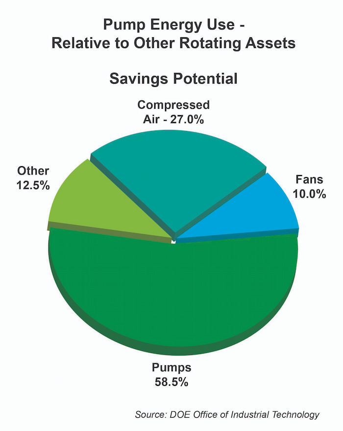
Figure 3. According to the DOE, pumps consume 50 percent of the electrical energy used by rotating assets in a typical plant.
For pumping system performance monitoring, one can specify that some of the same sensors used in a pump protection system also provide information in a pump performance monitoring system. One can use suction and discharge pressure sensor information, along with flow meter information and pump power and rotational speed information, to help designers/operators determine the pump’s performance relative to its best efficiency point (BEP). In some cases, operators may determine that the current pump system cannot meet current operating requirements or is not sized correctly and needs to be reworked or replaced to achieve energy and maintenance cost improvements.
Accurate flow rate data provides key indication of pump efficiency. Suitable flow meters already in line with the pump may often be used to provide pump flow performance information to compare with pump power and speed information over time. Ideally, the role that a process flow meter takes in life-cycle pump performance monitoring is best specified during the design of the process and the pumping system.
If no flow meter is suitably positioned to provide flow rate information at the pump, portable, ultrasonic flow meters can often be temporarily mounted outside existing piping near the pump. These clamp-on ultrasonic flow meters are convenient, but care needs to be taken to follow installation requirements to ensure getting usable flow rate data that fits performance monitoring needs. It is critical that the installed flow meter have good calibration history to ensure that data is accurate enough to represent the true flow rate though the pump.
Coriolis flow meters can be installed with little regard for upstream and downstream flow profiles, even on large pipes. Today’s Coriolis flow meters can provide traceable flow accuracies of ±0.05 percent. With high speed EtherNet/IP, fieldbus or HART communications, they provide not only mass and volume flow information but also temperature, density and viscosity. Other diagnostics related to voids or gas in fluid, such as leaking seals, that can impact pump performance are available in Coriolis meters.
Thermodynamic Monitoring
One widely accepted pump efficiency testing method that requires no flow measurement is the thermodynamic system. It employs the thermodynamic method detailed in ISO 5198 –1987 and the Code of Practice for Pump Efficiency Testing by the Direct Thermodynamic Method, by The Pump Centre, U.K.
The method involves insertion of high accuracy temperature probes and pressure transducers on both the suction and delivery sides of the pump to measure the differential water temperature and pressure. The energy lost due to the inefficiency of the pump is measured by the differential head and differential temperature across the pump. Neither the flow rate nor the power absorbed by the pump needs to be measured.
Where the shaft power absorbed by the pump can be determined, the flow rate may be calculated from the power absorbed, the differential head and the measured efficiency. This is applicable for well-defined fluids (such as water).
Pumps are vital, expensive systems that consume a great deal of energy and are expensive to rebuild or replace. Adding a few sensors to a pump system can help operators make pumps run more efficiently and uncover problems before they become too serious.
Pumps & Systems, May 2012
Calculating System Efficiency
The system efficiency, as designed by the power transfer in and out of the diagram in Figure 4, is:
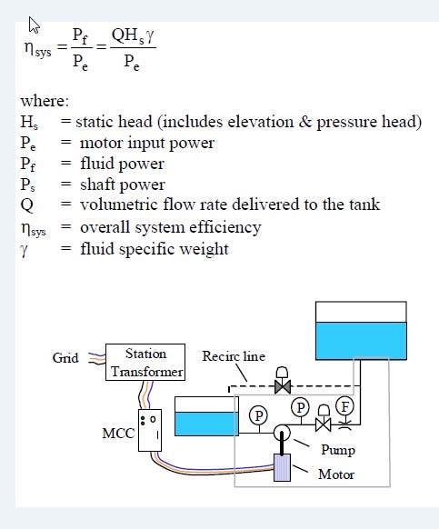
Figure 4. System efficiency
The flow rate is the net flow between tanks (ignoring recirculation flow). The head is the elevation difference between the tanks, or static head (implicitly ignoring friction losses). This is true system efficiency—it overlooks the details and sees only the big picture. This approach can be quite useful. However, it does not work for all situations. For example, the equation will produce a system efficiency of zero for a closed-cycle circulating system (with no static head).
