
AC Circuit Loads
Last month we discussed the relationship between voltage and frequency and tried to make that somewhat complex three phase sine wave a bit more understandable. This month we will quickly look at the load types that comprise a typical AC circuit.
Three basic loads occur in AC circuits-resistive, inductive and capacitive (and various combinations of the three). As it sounds, a resistive load consists purely of a resistance. Electrical resistance is simply a measurement of the opposition to the passage of current (electrons). Resistance is directly proportional to the internal resistivity of the material and its length and is inversely proportional to its cross-sectional area. Resistive circuit examples include water heaters, irons, electric ranges and even incandescent lighting-almost anything that is designed to generate heat.
Inductive loads, on the other hand, produce induced currents that oppose the flow of primary current in the circuit. This opposition to current change is different than resistance and is called reactance. Inductive circuit examples include electric motors, generators, solenoids and transformers.
Capacitive loads act exactly opposite of inductive loads and retard the flow of voltage. Examples include true capacitors (condensers), piezoelectric devices and metal oxide semiconductorsThese three loads have a very different effect upon the flow of voltage and current in an AC circuit.
Resistive Circuits
In the case of a resistive load, AC loses much of its mystique and behaves much like DC. Although there is no such thing as a purely resistive AC circuit, many are close enough that they will follow Ohm's law (I = E/R where I is current in amps, E is voltage and R is resistance in Ohms). Figure 1 shows a simple circuit with a 60 ohm resistance fed by 120 VA
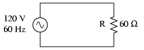
Figure 1
Using Ohm's law we can calculate the current in the circuit to be 2 amps. The power that the circuit dissipates (as heat) is simply the product of volts times amps, or 240 watts. If we did not know the voltage in the circuit we could calculate it by measuring the current. If I is 2 amps then E = IR or 120 V. The reason that these calculations are so simple can be explained by the relationship of the voltage, current and power curves seen in Figure 2.
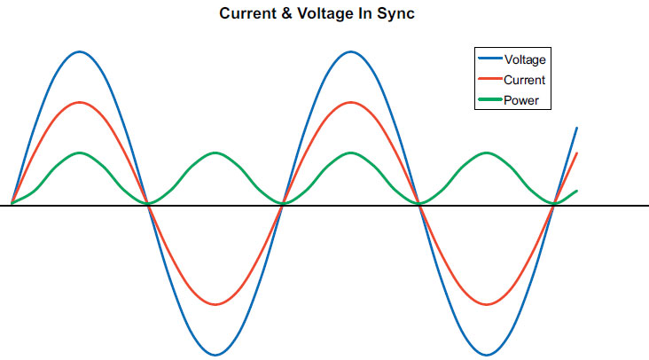
Figure 2
Figure 2 shows the flow of voltage (blue), current (red) and power (green) in a simple resistive circuit such as the one shown in Figure 1. In a purely resistive circuit, voltage and current rise and fall together in a synchronous fashion. The reason this occurs is that a resistance continuously opposes the flow of current in a circuit regardless of whether the voltage is DC or AC. Because of this continuous opposition, current flows in phase with voltage. At every point above the x axis, both voltage and current are positive, and at every point below the x axis, both are negative. The green curve represents the power (in watts) dissipated as heat in the circuit and is the product of the voltage and current at any point on the x axis.
Note that the power curve is always positive except at those points where voltage and current pass through zero. Even when both current and voltage are negative, power is still positive because the product of two negative quantities results in a positive quantity. Therefore, power is consumed at all points except those where the waves pass through zero. Even though the wave forms are still a bit complex, their synchronous relationships make a resistive circuit relatively understandable.
Inductive Circuits
Inductive loads could not be more different. A new dimension, known as inductance, and a new quantity, known as reactance, cause this type of circuit to behave in a fashion different from the simple resistive load. This different behavior is due to the positive and negative fluctuation of the AC sine wave.
Figure 3 is an example of a simple inductive circuit that consists of an AC source connected to an inductor. In this example, the inductor is a coil of wire consisting of several loops. When AC flows through a coil, a magnetic field is created in and around the coil and it increases and decreases in proportion to the primary current flowing through the circuit. This changing magnetic field induces a secondary voltage in the coil, which gives rise to secondary current that opposes the primary current. This process is known as self induction or self inductance. In a DC circuit this opposition arises only when the voltage is switched on or off. Once a DC inductive circuit is energized, current flows steadily in a single direction and no secondary current is induced.
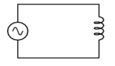
Figure 3
Figure 4 (from Collaboration for NDT Education) provides a clearer picture of how this occurs. In this example, primary current (red) is shown flowing clockwise through the loops in the coil. Its flow gives rise to a magnetic field (blue) in the first loop. The magnetic field induces a secondary current (green) in the second loop that flows counter clockwise. The counter-clockwise flow of the secondary current (often called back emf) opposes the normal flow of current and causes current to lag voltage in the circuit. This opposition to a change in primary current is known as reactance.
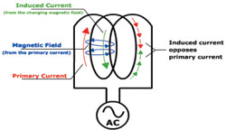
Figure 4
Figure 5 shows the flow of voltage (blue), current (red) and power (green) in a purely inductive circuit. The opposite flow of the induced secondary current impedes the flow of primary current and causes it to lag voltage by 90 deg or one quarter cycle. The power curve shows the overall effect of reactance. Note that it is positive during every other quarter cycle and negative during the quarter cycles in between. The RMS values of the positive and negative portions of the curve are also equal.
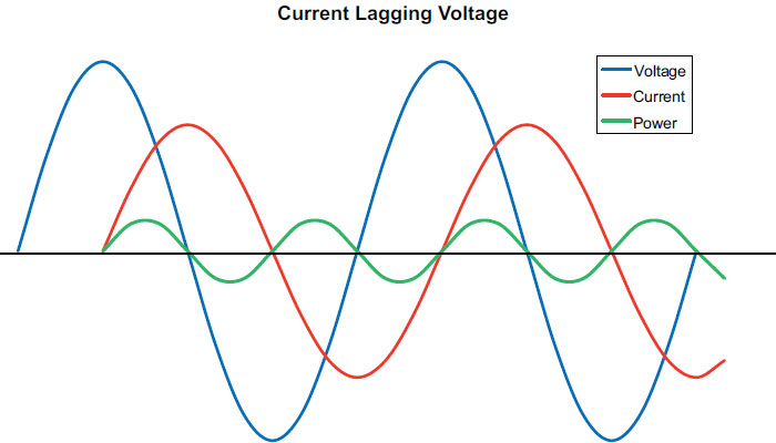
Figure 5
During the positive quarter cycles, the circuit is storing power as the magnetic field and during the negative cycles the field dissipates and returns power to the source. Therefore, a purely inductive circuit consumes no energy. The degree to which the secondary current or back emf impedes the flow of primary current is called inductive reactance (XL) and, like resistance, it is measured in ohms. Shortly, we will show how inductive reactance can be used to help redefine Ohm's law for use in AC circuits.
Capacitive Circuits
We will end this part with a quick discussion of purely capacitive circuits. A capacitor is a device that can store an electric charge, and the energy stored is equal to the work done to charge it. It consists of two plates separated by an insulating sheet called a dielectric. When connected to a DC voltage, one plate acquires a negative charge while the other acquires a positive charge, but no current flows through it once the capacitor is fully charged. If that same capacitor is connected to an AC voltage, an alternating current will flow continuously.
Figure 6 is a simple, purely capacitive AC circuit. A charge cannot flow between the two plates since they are insulated from each other, so it seems a bit unusual that a continuing AC current exists in the circuit. The reason current flows in a capacitive circuit when AC is applied is because those charged plates change their polarity each time the AC sine wave reverses direction. This causes the charge to flow to and from the two plates. Therefore, the two plates of the capacitor are continuously charging and discharging and current flows continuously.
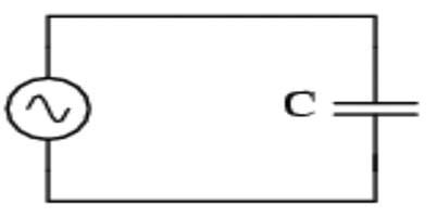
Figure 6
Figure 7 shows the flow of voltage and current in a purely capacitive circuit. The flow relationship is exactly opposite that of the inductive circuit and current is seen leading voltage by 90 deg. Although power is not shown, it would look like the power curve in the inductive example, and the circuit consumes no power. The degree to which charging impedes voltage is called capacitive reactance (XC), and it is measured in ohms like resistance and inductive reactance.
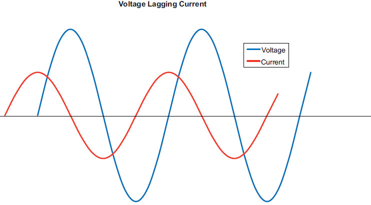
Figure 7
RLC Circuits and Impedance
Although some circuits consist of a single load type, most are combinations and are referred to as RLC circuits. Because of the influence of the inductive and capacitive loads, Ohms law (E = IR) does not apply. Instead resistance (R) is replaced with impedance (Z), and impedance takes into account both inductive and capacitive reactance. The equation takes the form of E = IZ and Z is equal to √R2+(XL-XC)2 (where R is resistance, XL is inductive reactance and XC is capacitive reactance). The square root sign encompasses the entire equation. As you can see, XC is subtracted from XL as its voltage lagging effect compensates for the current lagging effect of XL. If the two are equal, they cancel each other and the circuit is purely resistive. In circuits where XC is greater than XL, the negative sum is squared and produces a positive number that is added to the square of R. The square root of that sum gives us the circuit's actual impedance.
Power factor describes how effectively the loads in a circuit can use the power available and is directly related to inductive and capacitive reactance. We will not discuss power factor here because I have covered this important AC topic in the past. Please see my June and July 2007 P&S articles on power factor for a detailed discussion.
Next month we will explore mutual induction and the versatility of that mutual induction machine known as the transformer.
Pumps & Systems, August 2010
