A large utility company confronts alignment of a 5,000-horsepower motor.
Installation and setup of a pump and motor can be easy for small systems. Both can be lifted with relatively small equipment and do not require the use of rented cranes, which can cost thousands per day due to the load requirement.
Of the numerous installation steps, alignment is crucial. Poor alignment can cause excessive vibration, bearing wear, coupling fatigue or complete coupling or shaft failure. All add to maintenance costs and increase the risk of an unplanned outage. How can a motor be aligned if the rotor cannot be turned?
Recently, a large utility company in the northwest contacted a motor manufacturer requesting help with this dilemma. The vertically-mounted motor driving a circulation water pump was rated at approximately 5,000 horsepower and had a hydrodynamic upper thrust bearing that would not allow them to freely turn it by hand (typical minimum speed for a hydrodynamic bearing to develop an oil film is about 100 rpm). The motor rotor weighed 22,000 pounds. The motor rotor/pump coupled together weighed 47,000 pounds.
The customer had the overhead crane capacity to lift the entire motor (20 tons) that could be used, if necessary. The customer had been using the chain fall method with limited success, achieving approximately 0.005 inch of run out, which was causing vibration and bearing wear in the pump shaft guide bearings. A custom alignment device was developed, allowing the user to alleviate difficulties with rotating the motor shaft and obtain proper alignment with relative ease.
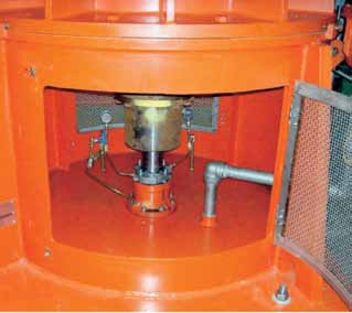
Figure 1. Motor shaft extension viewed through a pump stand opening. Dial indicators used to measure run out can be seen.
Alignment Difficulties
During alignment, the motor rotor must be spun by hand since it must turn slowly enough to obtain accurate run out readings. Alignment typically must be less than 0.001 inch from motor to pump couplings. On large pump/motor combinations greater than 2,500 horsepower, the process becomes compounded since access to the shaft can be limited due to pump stand design and cramped working space.
Most rotors in this horsepower range are too large to freely rotate by hand unless the upper bearing is an antifriction type roller bearing. Once the motor is in place, there is not enough space to access the bottom shaft extension to be able to use a jack or other method to lift the rotor. Most sites do not have the overhead crane capacity to lift the rotors, which can exceed 20,000 pounds for the motor rotor and 40,000 pounds for the motor and pump train together.
Some sites are able to use the chain fall method to align the motor and pump, as the user originally did in this case. If a capable bridge crane is present, it can lift the rotor using a chain fall to the top of the shaft, relieving enough weight from the upper bearing to allow the rotor to be turned with a breaker bar through the chain or upper rigging. This method, depending on the style of upper bearing, can allow up to 0.015 inch radial movement of the rotor making it difficult to keep the run out between the pump and motor under 0.001 inch. The lower bearing in most cases has more clearance than the upper, generally around 0.030 to 0.040 inch, allowing for more movement of the shaft.
If this movement is not controlled and the shaft is not kept centered in both the upper and lower bearings, then the carefully planned and executed alignment can be ruined once the motor is energized. The motor will attempt to center itself due to the hydrodynamic forces.
Another hazard with using an overhead crane, especially if vertical travel is not easily controlled, is damaging the upper thrust faces or the shaft itself by lifting the rotor too much. This is a difficult process to perform when the operator is using a radio controlled crane and is standing at the bearing, much less if the crane operator is 30 feet away.
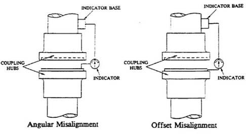
Figure 2. Typical setups for measuring angular and offset misalignment
Requirements in an Ideal Scenario
How can a rotor be turned by hand while keeping the shaft centered since alignment must be performed every time the motor or pump is removed and serviced?
This question was posed by a customer who had the overhead crane capacity but was not achieving the desired run out between the rotor and pump, which was affecting the operation of both pieces of equipment. Concerned with the issue, the customer required the following:
- The rotor must rotate freely with hand power although a breaker bar could still be used.
- A method must be present to center the shaft and hold it in place in both the upper and lower bearings.
- The lift of the rotor must be controlled.
- Most important, the method must achieve desired run out.
Using a device on the shaft extension and lifting the rotor from the bottom proved prohibitive due to the reasons outlined above. The device would need to lift the rotor from the top.
Solution
It became apparent that the fixture would need to be capable of lifting the pump and motor coupled together to perform final alignment checks. This doubled the capacity requirement from 25,000 to 50,000 pounds. The device would need to be stiff enough to limit vertical movement to prevent the rotor from binding when turning and bulky enough not to slip or deflect once the rotor was lifted.
The simplest solution proved to be the best. The final design used a table to directly lift the rotor from above and support the weight on a heavy roller bearing. This allowed the user to slowly turn the rotor with a large socket wrench (as designed). Portable hydraulic power was used to transfer the weight from the motor upper thrust bearing to the lifting table. The table also included jacking provisions to center the shaft in the upper bearing, since the rotor would attempt to center itself under running conditions. To center the shaft in the lower bearing and restrain it while turning, smaller jacking blocks with Micarta bumpers were bolted to the bottom bearing bracket and then adjusted until contact was made with the shaft.
The full process was as follows:
- A lifting cap was installed on the top of the shaft to enable jacking without damaging the shaft.
- The lifting table was lowered over the upper bearing assembly (extra care was taken during this step as the entire upper bearing was exposed).
- An all thread bolt was inserted through the table and secured in the lifting cap.
- The hydraulic power unit was placed over the all thread bolt and supported on a roller bearing, then secured with a nut.
- Lower bearing blocks were installed and both the upper and lower bearings were checked for center. If not centered, the shaft was jacked into place.
- The hydraulic power unit was pumped to shift some of the load to the roller bearing and “lock” the rotor in place, preventing subsequent radial movement.
- The shaft center was rechecked to ensure that no movement occurred due to the roller bearing “settling.”
- While applying torque to the shaft with either a strap or socket wrench, the hydraulic power unit was pumped until the shaft rotated easily. A dial indicator was used to measure the vertical travel of the shaft, ensuring that damage did not occur to the upper thrust faces from excessive lift.
- The rotor was then ready for run out checks and slow roll operation.
- The rotor was able to be turned using hand power on the lower shaft extension.
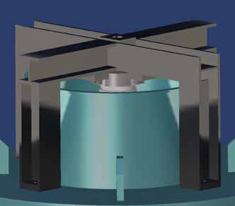
Figure 3. Graphic of the lifting table resting on the upper bearing bracket, and the upper shaft extension can be seen directly under the table.
In Actual Operation
The device worked better than the designed expectations for the utility company because the user was able to forgo the large socket wrench and turn the motor rotor by hand using the shaft extension on the bottom. This allowed the operator to turn the rotor at the speed necessary to get the required run out readings. Final alignment between the pump and motor was less than 0.001 inch.
Pumps & Systems, October 2011