
Materials expand when heated and contract when cooled. Pipes are not immune to these laws of nature, so they will also expand and contract with varying temperature.
This article will introduce the basics of stresses and anchor loads induced by thermal expansion. To stick to the basics, a straight piece of restrained pipe will serve as the example. We will also look at some available options to reduce the pipe stresses and anchor loads.
Stresses Induced by Thermal Pipe Expansion-The Basics
We will start with some definitions of commonly used flexibility terms. Stress is defined as force per unit area in a material:
S = F/A (Equation 1)
S = Stress (psi-can be negative or positive)
F = Force (lbf-can be negative or positive)
A = Area (square inches)
Strain is defined as a percentage or ratio of a change of length divided by the original length:
ε = ΔL/Lo (Equation 2)
ε = Strain (inch/inch-can be negative or positive)
ΔL = Change in length (inches-can be negative or positive)
Lo = Starting length (inches)
Stress and strain are related by Hooke's Law:
S = Eε (Equation 3)
S = Stress (psi)
E = Young's Modulus (psi)
ε = Strain (in/in)
Piping materials exhibit nearly linear expansion and contraction with temperature. The rate of thermal expansion and contraction is characterized by the coefficient of thermal expansion, a, and has units of in/in-°F, or strain per degree Fahrenheit. The change in dimensions of an object is then:
ε = a (T2-T1) (Equation 4)
ε = strain (in/in)
a = Coefficient of thermal expansion (in/in-°F)
T2 = End temperature (°F)
T1 = Starting temperature (°F)
If the object is a straight bar or pipe, the more familiar form of this equation is:
ΔL = aLo(T2-T1) (Equation 5)
ΔL = Change in length (in)
Lo = Initial length of pipe (in)
Consider a 6 in diameter steel (ASTM A53) pipe, 100 ft long, anchored at one end. The pipe is empty, and the inside is at atmospheric pressure. The temperature is increased to 200 deg F above ambient. The expansion of the pipe from equation (2) is:
a = 6.33 x 10⁻⁶ in/in-°F
Lo = 1,200 in
T2 = 270 deg F
T1 = 70 deg F
ΔL = (6.33 x1 0-6 in/in-°F)(1,200 in)(270°F-70°F)
= 1.52 in
If the pipe is installed at an ambient temperature of 70 deg F, and the temperature of the pipe increases to 270 deg F, we can expect about 1.5 in of expansion in the 100 ft unanchored run. Assuming the pipe is properly supported along its length, the stresses will remain well below the yield point of the steel.
If the pipe is now anchored at both ends and subjected to the same conditions, the stresses in the pipe will significantly increase. The anchors will prevent the pipe from expanding during the temperature rise. The result will likely be failed anchors, a buckled pipe or both.
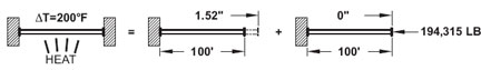
Figure 1. The anchor forces in a 6 in. pipe undergoing thermal expansion
The pipe is in static equilibrium, but the only forces acting on it are the pipe anchors (static indeterminacy). The material properties can tell us how much force and stress will build in the pipe. The reaction force of the anchor must equal the amount of force needed to contract the pipe by 1.5 in (the amount of thermal expansion).
Substituting equations 1 and 4 into equation 3, stress is related to thermal strain by:
F/A = Ea (T2-T1) (Equation 6)
To solve for the force in the anchors, equation 6 can be rearranged as:
F = AEa (T2-T1) (Equation 6)
Notice that the initial length and change in length do not matter in calculating the stresses and forces. For our 6 in diameter, 100 ft pipe restrained by the anchors:
A = 5.581 in2
E = 27.5 x 10⁶ lbf/in2
a = 6.33 x 10⁻⁶ in/in-°F
T2 = 270 deg F
T1 = 70 deg F
The stress along the longitudinal axis of the pipe is then:
S = Ea (T2-T1)
= (27.5 x 10⁶ lbf/in2)(6.33 x 10-6 in/in-°F)(270°F-70°F)
= 194,315 lbf/5.581 in2
= 34,815 psi
The force in the anchors is:
F = stress x pipe area
F = (5.581 in2)(34,815 lbf/in2)
= 194,315 lbf (anchor load)
If the pipe has a 2 in diameter, the area is 1.075 in2, the reaction force is 37,410 lbf and the resulting axial stress would be the same, 34,815 psi. The stress in this simple case only depends on the material properties and the temperature change; however, the anchor loads are also dependent on the pipe section dimensions.
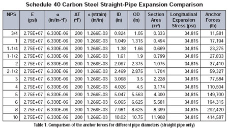
Table 1. Comparison of the anchor forces for different pipe dieameters (straight pipe only)
A rigid connection to a pump or other piece of equipment behaves like an anchor-to a point. The Hydraulic Institute and API publish standards for allowable pump nozzle loads, and manufacturers of other equipment will have limits on connector loads. It should now be apparent that thermal expansion in piping systems must be addressed during the design of any system subjected to temperature changes.
Relieve the Stress
Now that we have an idea of the magnitude of the stresses and anchor loads in a pipe system, there are several ways to help the situation. The simplest method is to take advantage of the pipe's natural flexibility. If this is not practical, consider pipe expansion joints.
Pipe Flexibility
Pipes bend, even under their own weight. The longer the pipe, the easier it is to bend. If a pipe is bent within its elastic limit (no permanent deformation), it will behave like a spring and return to its original shape after the load is removed. If the elbows and anchors on a pipe system are arranged to allow movement, the forces will be much less than a straight run. Consider Figure 2 with an empty 6 in pipe.
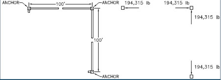
Figure 2. Arrangement of empty 6 in. pipe and three anchors, and the resulting anchor loads
(dead weight not included-the forces shown are due to expansion only)
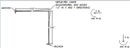
Figure 3. Arrangement of empty 6 in. pipe and two anchors, and the resulting anchor loads
(dead weight not included)
The anchor loads and stresses are much less than in the straight pipe case,but there are tradeoffs. The alternate layout introduces moment (torque) loads on the anchors. The pipes also move 1.5 in, which may not be acceptable for a given system. Geometry can affect this arrangement-if one leg is shorter, the forces and moments will be higher. Calculating the stresses and anchor loads without a computer is also a challenge. Pipe flexibility calculations were significant research topics in the early 20th century, and several papers were devoted to the subject before pipe stress analysis software became widely available.
Expansion Joints
The geometry of the pipe system will usually determine the anchor loads; however, not every piping arrangement will permit the pipe to naturally flex. A confined space or tunnel is an example. In cases like these, pipe expansion joints are necessary. Expansion joints may employ bellows, hose and braid, ball joints, flexible couplings or sliding mechanisms. All have their unique properties that are appropriate for a given system.
For example, we will consider the case of installing a bellows expansion joint in our 6 in pipe run. If we now consider the pipe is running full, insulated and is under a pressure of 150 psi, the anchor loads are calculated as:
Initial Temperature = 70 deg F
Operating Temperature = 270 deg F
Bellows Effective Area = 40 in2 (from manufacturer's data-this is the area calculated from the average diameter of the bellows convolutions)
Test Pressure = 150 psi
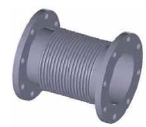
Figure 4. Belows expansion joint
The anchor load is then the sum of the pressure thrust, the spring force and the friction forces of the pipe guides. For this example:
Bellows pressure thrust = 150 psi x 40 in2
= 6,000 lb
Bellows spring force = Calculated movement (1.5 in) x spring rate (555 lb/in-from manufacturer)
= 832.5 lb
Friction force = Coefficient of friction (assumed at 0.3) x weight of full pipe and insulation (36.5 lb/ft x 100 ft)
= 1,095 lb
Total Anchor Load = 6,000 + 832.5 + 1,095
= 7,927.5 lb
This is still a substantial anchor load, but much less than a pipe without an expansion joint. If the pressures and temperatures permit, a hose and braid expansion joint may be used. The anchor loads will be substantially less in this case.
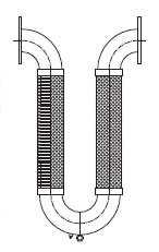
Figure 5. Flexible loop expansion joint
The anchor loads imposed by a flexible loop expansion joint are simply the movement multiplied by the spring rate of the joint. Using the previous example, the anchor load is:
Anchor load = Axial spring rate (60 lb/in-from manufacturer) x 1.5 in movement
= 90 lb
As in the pipe flexibility example, the dead weights of the pipe, insulation and fluid are not included in the anchor loads. Only the forces imposed by the expansion joints are shown.
Conclusion
It is important to remember that only two examples of expansion joints are presented here. It would be well worth the time and effort to become familiar with the advantages and limitations of other expansion joints available.
Temperature changes will impose stresses on pipes. There is no way around it, but the effects of thermal expansion can be accommodated by careful arrangement of anchors and the proper choice of expansion joints.
