
Editor's Note: This is the second in a six-part series on centrifugal pump efficiency. For other articles in this series, click here.
Early centrifugal pump design was heavily influenced by turbine technology during the mid to late 1800s. Specific speed was first applied to centrifugal pumps in the latter 1800s and was a modified version of one developed for water turbines. Many pump designers see specific speed as the most important contributor to centrifugal pump design. It allows the use of existing design and test data to design similar higher and lower flow pumps because the specific speed of a pump is independent of its size.
An Index Number
As Terry Henshaw stated in “Centrifugal Pump Specific Speed” (Pumps & Systems, September 2011), the definition of specific speed can be confusing. It is best to think of it as an index number that can predict certain pump characteristics. Viewed this way, specific speed can be useful when selecting a pump for a particular application and predicting premature failure due to off best efficiency point (BEP) operation.
Figure 1 shows the relationship of the numerical value of specific speed to an impeller’s geometric profile.
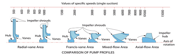 Figure 1. Pump profile comparisons (courtesy of www.pumpfundamentals.com)
The lower values (500 to 1,500) on the left of the figure describe the geometry of the radial vane impeller while the higher values (9,000 and higher) on the right of the figure equate to true axial flow impellers (propellers). A radial vane impeller discharges 100 percent of its flow perpendicular to its suction, usually with a low flow-to-head ratio.
An axial flow impeller discharges 100 percent of its flow along the same axis as its suction with a high flow-to-head ratio. Mixed flow impellers (4,000 to 8,000) exhibit both radial and axial characteristics, discharging between the radial and axial angles with a high-flow-to-moderate-head ratio.
Those between radial and mixed flow (1,700 to 3,500) are known as Francis vane impellers. This design discharges radially, but the transition from inlet to outlet is more gradual and results in the highest efficiency. The cross sectional pictures in Figure 1 show that, as specific speed increases, the impeller inlet or eye diameter increases and eventually approaches or equals that of the vane outlet. The flow passages also increase in size at a corresponding rate.
Pump Design
While this is a nice comparison, pump designers may question its usefulness. An equation (shown below) that relates specific speed and its corresponding geometry to real application values of head, flow and rotational speed was developed.
Ns = n x √Q / H0.75
Where:
Ns= specific speed
n= pump rotational speed (rpm)
Q= flow (gallons per minute)
H= head (feet)
This equation can be used to determine which impeller design best matches the application requirements.
Impeller Geometric Design
An impeller is needed that will produces 900 gallons per minute (gpm) at 190 feet of head. If these values are entered as Q and H in the equation with a motor speed of 3,600 rpm, the specific speed is 2,110. The geometry would be similar to the Francis vane impeller (Figure 1 at the 2,000 point).
If the motor speed is lowered to 1,800 rpm, an impeller with a specific speed of 1,055 would be required for the same flow and head. Its geometry would be similar to the radial vane impeller (beneath the 1,000 point). At 1,200 rpm, specific speed is 703, and the impeller would look like a hybrid of the two impellers seen to the left of Figure 1. Specific speed is directly proportional to rotational speed when head and flow remain constant. However, the specific speed of a single impeller design does not change with a change in rotational speed. It remains constant because flow and head change in accordance with the affinity laws.
Pump Performance
Figure 2 illustrates how specific speed can provide predictions about the performance of an impeller design. Experience dictates that a pump’s efficiency reaches its maximum at specific speeds between 2,000 and 3,000, although favorable efficiency can occur at almost any specific speed. Also, the area around the BEP tends to be flatter and broader as specific speed decreases.
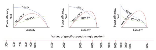 Figure 2. Specific speed and pump performance curves (courtesy of www.pumpfundamentals.com)
Pump efficiency also increases with pump rotational speed, especially high speeds. The increase is not as pronounced at 3,600 rpm and below. Specific speed also affects head-capacity curve shape. Low specific speeds (500 to 1,500) produce flat curves. High speeds (6,000 and higher) produce steep curves. Intermediate speeds produce curves between the extremes. Curve shape will be discussed further in another column.
Power Curve
Specific speed provides another prediction—the characteristics of the power curve. At specific speeds below 4,000, power drops as flow is reduced and is at its minimum at shut off head. The power curve remains relatively flat, across the head-capacity curve—between 4,000 and 4,500—and rises toward shut off at specific speeds of 5,000 and higher. At speeds above 9,000, the power curve becomes extremely steep and almost parallels the head-capacity curve.
Impeller Dimensions
Once geometry is chosen for the impeller, the pump designer can conduct a mathematical analysis that will allow him to derive all the impeller dimensions and angles needed to meet the design point. This is an arduous task. To review a comprehensive example of how this is done, see pages 2.23 - 2.31 of the second edition of the Pump Handbook (McGraw-Hill).
Conclusion and Other Resources
The Ns ranges cited in this column are not cast in stone. They can be narrower or wider or vary based upon the design characteristics of a pump. They are, however, a good rule of thumb.
A great book on centrifugal pumps was written by John Richards, editor of the San Francisco based journal Industry, in 1894. He was the first writer to point out that centrifugal pumps do not operate via centrifugal force since there is no such force in nature. Centrifugal Pumps: An Essay on Their Construction and Operation, and Some Account of Their Origin and Development in This and Other Countries is available as a free download at Google Books. Some of the knowledge about impeller vane shape from the 1850s is amazing.
