


Q. What are the parameters for pump baseplate design, and why must baseplates be grouted in place?
A. A baseplate is the structure to which the pump, motor, gearbox, and all auxiliary equipment are mounted. The purpose of a baseplate is to provide a foundation under a pump and its driver that maintains shaft alignment between the two pieces of equipment. This baseplate must:
• Survive handling during transportation to the installation site
• Be capable of being installed properly with minimum difficulty
• Allow for the initial mounting and alignment of the equipment
• Allow for the final alignment of the mounted equipment
• Control spillage
• Allow for the removal and reinstallation of equipment
To meet these requirements, an absolutely rigid baseplate is not necessary. At the same time, the baseplate must not be permanently deformed after the equipment is mounted at the manufacturing facility. Compliance with these design criteria, in conjunction with proper installation procedure, will contribute significantly to meeting the functional requirements.
Any baseplate must be designed to satisfy numerous functional requirements. To ensure correct design of the baseplate, all application parameters must be reviewed—including equipment selection, installation and operational requirements. For standardized pump ranges with predefined and specific applications, the equipment manufacturer should have taken all these factors into account. For customized pump applications, these fundamentals should be reviewed at the time of proposal.
The grouted baseplate shown below is designed to allow the grout to be poured underneath the base. The grout placed inside the base contributes to the baseplate's installed rigidity and damping. See Figure 1.3.8.2.1a.
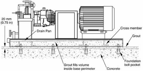 |
| Figure 1.3.8.2.1a. Grouted baseplate, fabricated steel |
The cross members used on the baseplate in Figure 1.3.8.2.1a are normally designed to lock into the grout and further resist any deflection or vibration of the baseplate. Typically, the cross member geometry chosen to achieve this is an L-section (shown), a T-section or an I-section.
If the baseplate is a closed design (i.e., the grout cannot be poured inside the baseplate perimeter due to the presence of a drain pan or deck plate), then grout and vent holes must be provided to allow the grout to be placed inside the base.
The grout used may be either cementitious or epoxy-based. The surface preparation required for a baseplate to successfully bond to the grout is different depending on which grout will be used. It is therefore important that the vendor and customer agree in advance which type of grout will be used.
The baseplate described and shown in Figure 1.3.8.2.1a is typical of a fabricated baseplate. Cast-iron baseplates are another type of grouted baseplate. The ability to integrally cast in features such as bracing, grout holes and sloping surfaces provides a highly functional and economical solution for many applications.
For additional details on baseplates see ANSI/HI 1.3 Rotodynamic (Centrifugal) Pumps for Design and Application.
Q. What are mixed flow impellers, and when are they used?
A. Impellers described below are used in a wide variety of services. For any given service, one type may be preferred. In most cases, however, the users' and manufacturers' experience is the best guide for making a selection.
Rotodynamic pump designs are generally described as any of three types: radial flow, mixed flow or axial flow. For examples, see Figure 1.3.4.1. Radial flow impellers are designed so that the liquid exits purely radially, or perpendicular to the shaft centerline. They have lower specific speeds, in the range ns 10 to 50 (Ns 500 to 2,500), and most often are used for lower-flow, high-head applications.
As design flow increases, specific speed increases, and the impeller will become more axial in its configuration, with fluid flow in line with the shaft centerline. Fully axial impellers produce high flow rates with little head.
Between these two extremes, the liquid exit angle transitions from radial to axial as shown in Figure 1.3.4.1. These transitional designs are referred to as mixed flow impellers. They are used when the impeller specific speed is from 80 to 140 (4,000 to 7,000).
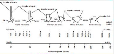 |
| Figure 1.3.4.1. General impeller types |
For more information on impeller design, see HI Standard ANSI/HI 1.3, Rotodynamic (Centrifugal) Pumps for Design and Application.
Pumps & Systems, December 2010
Pump FAQs® is produced by the Hydraulic Institute as a service topump users, contractors, distributors, reps and OEMs as a means of ensuring a healthy dialogue on subjects of common technical concern.