
Q. I understand the significance for properly configured suction piping, but what are the piping requirements on the discharge side of a rotodynamic (centrifugal) pump?
A. The maximum velocity at any point in the outlet (discharge) piping is 4.5 m/s (15 ft/s). This limit shall, however, be reduced if there is a check valve in the outlet piping that will generate a hydraulic shock when it closes. (Note that pump discharge nozzle velocity may exceed this value. Therefore, the straight discharge pipe length at the pump discharge nozzle, which will be the same diameter as the discharge nozzle, cannot be subject to this velocity limitation.)
System pipe friction losses, life cycle costs and process considerations normally dictate the size of the discharge piping and fittings. (If the liquid is a slurry, then the velocity in the discharge pipe may be higher to keep solids in suspension. See Appendix E.4 for slurry/solids pumping recommendations in the new HI Standard, ANSI/HI 9.6.6-2009-Pump Piping for Rotodynamic Pumps.)
Pipe fittings mounted close to the outlet (discharge) flange will normally have minimal effect on the performance or reliability of rotodynamic pumps. However, some pumps can be sensitive to flow-disturbing fittings mounted close to the pump outlet (discharge). This can result in increased noise, vibration and hydraulic loads. If in doubt, check with the pump manufacturer.
For most pumping systems, an inlet (suction) shut-off valve should be installed in the pump inlet piping for system isolation. An outlet (discharge) shut-off valve should also be installed in the pump outlet for system isolation. The shut-off valve is used in priming and when starting or stopping the pump for maintenance. Except for axial flow pumps, where the shut-off horsepower is excessive, it is advisable to close the shut-off valve just before stopping and starting the pump. This is especially important if there is no discharge check valve and the pump is operated against a high static head. In addition, for very high horsepower pumps or pumps with thermally sensitive liquids, it is advisable to throttle the pump to minimum flow just before starting or stopping the pump.
If a foot valve is not installed in the inlet (suction) pipe, then a check valve may be necessary between the pump and the shut-off valve to protect the pump from reverse flow and excessive backpressure. If expansion joints are used, they should be placed on the pump side of the check valve to dampen, and not transfer, closure slam. (Do not rely on an expansion joint to dampen the shock of check valve closure. Add a damper to the check valve when shock due to rapid closure of the check valve is likely.)
Submersible turbine well pumps must always have a check valve installed in the discharge line, no more than 7.6 m (25 ft) (for water at sea level) above the lowest liquid (pumping) level in the well or sump. This distance limit is necessitated by the vapor pressure limitation to ensure that a fluid void will not form under the check valve, which can cause a hydraulic shock or water hammer the next time the pump is started.
At higher elevations, higher temperatures and for liquids with different vapor pressures, this distance must be evaluated and will be less than the specified 7.6 m (25 ft). The discharge valve and check valve can be replaced by a triple-duty valve that provides both functions in a single body. Triple-duty valves also provide circuit balance capability and require shorter installed pipe lengths at reduced cost compared to separate valves. (Note that triple-duty valves may have a high energy cost associated with their use. This should be evaluated as a part of a life cycle cost analysis.)
Q. Multistage rotodynamic (centrifugal) pumps usually have all impellers facing in the same direction. This causes a large axial force in one direction that requires a large thrust bearing to support it. What can be done to reduce the axial thrust?
A. One approach is to reverse the direction of half of the impellers. Assuming a six stage pump, the first three stage impellers would face in one direction and the next three stages would face in the opposite direction. To accomplish this, the flow from the third stage impeller is routed out of the pump and returned to the inlet of the fourth stage impeller. This adds the complication of the external flow passage, but reduces the need for a large thrust bearing. This design is often found in axial split multistage pumps.
Another approach is to add a balancing drum on the rotor, which counter balances the axial thrust. The drum is usually the same diameter as the impeller wearing ring and has full discharge pressure on the side by the impellers. Leakage through this drum clearance is piped back to the pump suction end. The result is low residual thrust that requires a much smaller thrust bearing.
In a similar design a balancing disc can be used instead of a drum. See Figure 1.21.
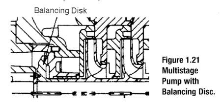
In this design the balancing disc is larger than the impeller wearing ring diameter and the discharge pressure will push the rotor to the left. When that happens, the flow past the disc increases and the pressure at the disc is reduced by the increased loss through the close clearance bushing at the shaft. The result is a self-adjusting arrangement that requires little thrust bearing capability.
